Input device

a technology of input device and input device, which is applied in the direction of static indicating device, propulsion system, instruments, etc., can solve the problems of large input device size, weak visual or auditory perception, and degrade the confirmation performance in operation, and achieve the effect of stable thrus

Inactive Publication Date: 2014-03-25
FUJITSU COMPONENENT LTD
View PDF12 Cites 41 Cited by
  • Summary
  • Abstract
  • Description
  • Claims
  • Application Information

AI Technical Summary

Benefits of technology

[0010]It is another object of the present invention to provide a small-sized input device having tactile sense stimulus capabilities and obtain a stable thrust.

Problems solved by technology

Meanwhile, when the operator operates on the display screen for a long time and becomes tired, the visual or auditory perception is weakened.
This sometimes degrades the confirmation performance in operation.
This leads to downsizing.
This causes the input device to be large in size.
This also causes the input device to be large in size.

Method used


Image

  • Input device
  • Input device
  • Input device

Examples


first embodiment

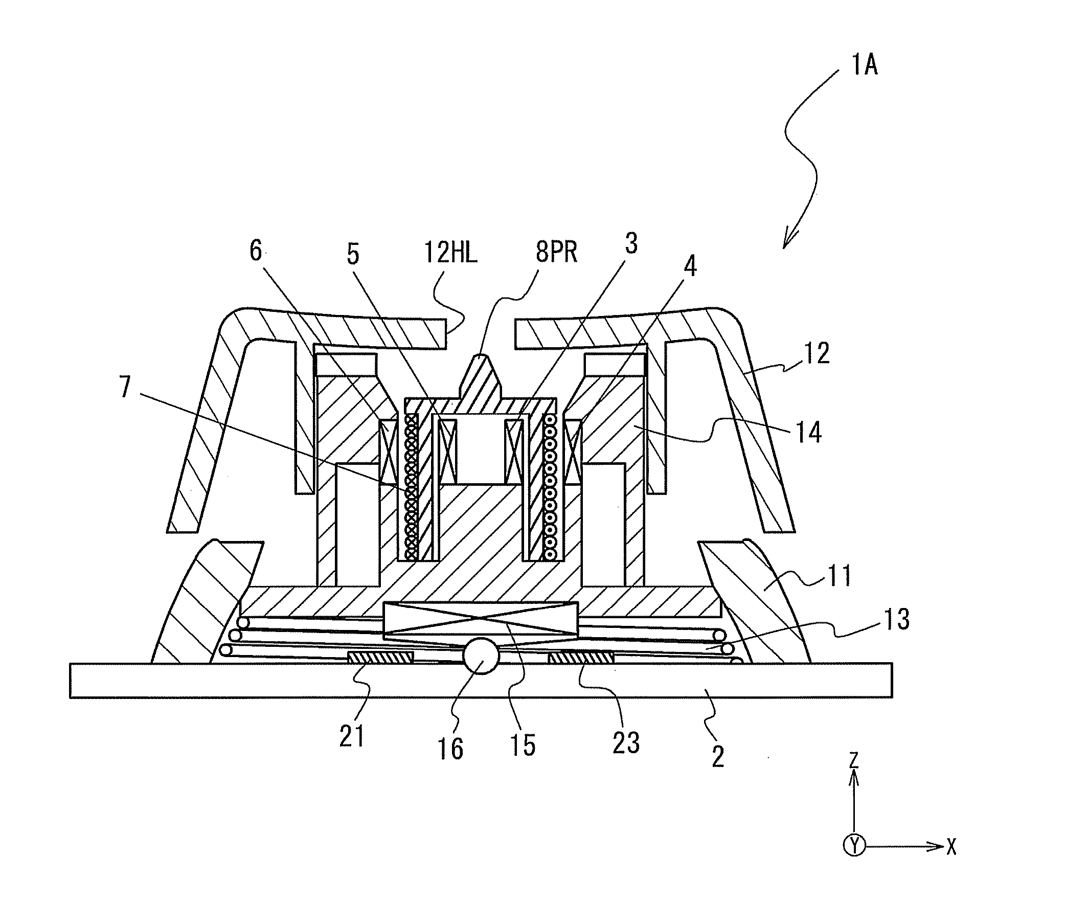
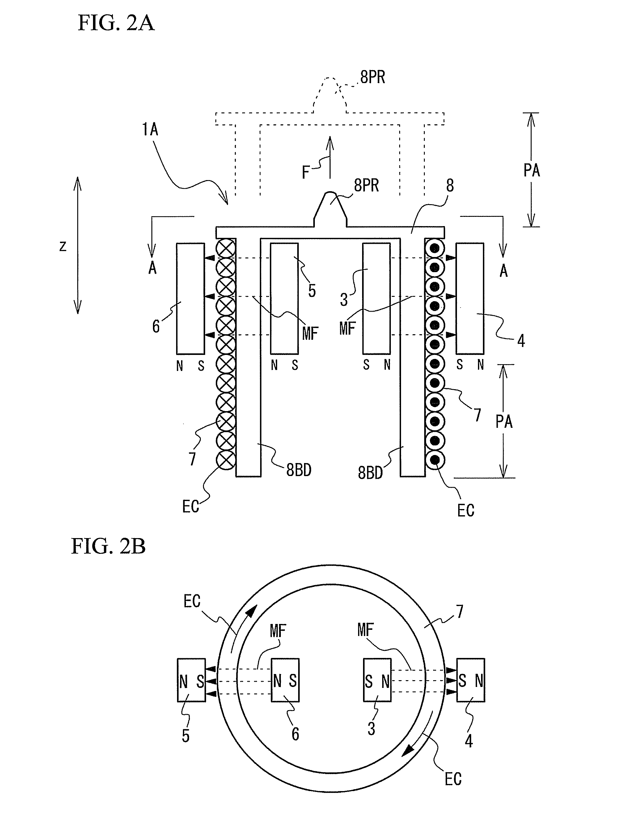
[0031]FIG. 2A and FIG. 2B show an input device 1A in accordance with a first embodiment of the present invention. FIG. 2A schematically shows main components of the input device 1A. FIG. 2B is a view showing positional relationship between a drive coil and permanent magnets when the input device 1A is viewed in a direction of A.

[0032]The input device 1A includes four permanent magnets 3, 4, 5, and 6, a drive coil 7, and a tactile sense stimulus member 8. The tactile sense stimulus member 8 substantially has a cylindrical shape, and an upper end thereof is closed. A projection 8PR is provided in the center of the upper end to project upwardly. There is a space in the tactile sense stimulus member 8 having an open lower end.

[0033]The drive coil 7 that serves as a second magnetic field generating portion is wound in a spiral manner on an outer surface of a body 8BD of the tactile sense stimulus member 8. Therefore, when the drive coil 7 is moved by the thrust, the tactile sense stimulu...

second embodiment

[0053]A second embodiment of the present invention will be described with reference to the drawings. Hereinafter, in the second embodiment, the same components and configurations as those of the first embodiment have the same reference numerals and a detailed explanation will be omitted. FIG. 7A and FIG. 7B show an input device 1B in accordance with the second embodiment of the present invention. FIG. 7A schematically shows main components of the input device 1B. FIG. 7B is a view showing positional relationship between the drive coil and the permanent magnets when the input device 1B is viewed in a direction of B.

[0054]The input device 1B is improved to have a greater thrust than that of the input device 1A in accordance with the first embodiment of the present invention. The input device 1B includes two drive coils 7-1 and 7-2, which are arranged on the left and on the right of the tactile sense stimulus member 8. Each of the drive coils 7-1 and 7-2 has the winding number greater ...

third embodiment

[0057]FIG. 9 is a view showing an input device 1C in accordance with a third embodiment of the present invention. In the input device 1C, the tactile sense stimulus member 8 of the movable range PA corresponds to the length of the permanent magnets 3 through 6 in Z direction (moving direction). In this input device 1C, the range (length) around which the coils can be wound is shorter, yet the coil is multiply wound to obtain a necessary magnetic field. The input device 1C can be downsized by setting the size in height to be almost equal to those of the permanent magnets 3 through 6 to obtain a desired thrust. In addition, if the size of the permanent magnets 3 through 6 is set longer, it is possible to arbitrarily lengthen the movable range PA of the tactile sense stimulus member 8.


PUM


Abstract

An input device including an operation portion to be operated by an external force, a signal generating portion that generates a signal according to a movement of the operation portion, and a tactile sense stimulus mechanism that applies a tactile sense stimulus to an object that applies the external force is provided. The tactile sense stimulus mechanism includes magnetic field generating portions, and a tactile sense stimulus member that is secured to a magnetic field generating portion.

Description

BACKGROUND OF THE INVENTION[0001]1. Field of the Invention[0002]This invention generally relates to an input device to be incorporated into an operating device such as a remote controller, mouse, or the like, which is used for inputting an instruction into an electronics device such as a personal computer, PDA, mobile telephone, automobile navigation system, television, and the like, and more particularly, to an input device that is capable of confirming that the user has performed a given operation.[0003]2. Description of the Related Art[0004]A mouse, for example, is coupled with a personal computer to output positional information or information that indicates a direction and move the pointer or cursor being displayed on the display to a given position. An input device is incorporated so that an instruction signal may be generated by the operating device such as the afore-described mouse. The input device is composed of an operating portion and a signal generating portion. The ope...

Claims


Application Information

Patent Timeline
Patent Type & Authority Patents(United States)
IPC IPC(8): H02K41/02G09G5/00G06F3/033
CPCH01H25/041G06F3/016G06F3/0338G06F3/0354H01H2239/024
Inventor HARADA, KEITASAKURAI, SATOSHIYATSU, NOBUO
Owner FUJITSU COMPONENENT LTD
Why Eureka
Try Eureka