Adaptive rendering of indistinct objects

a technology of indistinct objects and primitives, applied in the field of computer generated imagery or graphics, can solve the problems of system overloaded, large cost, and alter the number of primitives that are rendered and not the methodology used

Active Publication Date: 2014-03-25
ROCKWELL COLLINS INC
View PDF6 Cites 7 Cited by
  • Summary
  • Abstract
  • Description
  • Claims
  • Application Information

AI Technical Summary

Benefits of technology

[0008]One approach to rendering objects is a method. The method includes receiving data for one or more objects. The data for each object includes a fidelity code, wherein the fidelity code indicates object fidelity level. The method further includes computing pixels touched by each received object based on a pixel grid associated with the fidelity code of the object. The method further includes providing pixel data for objects having fidelity code indicating a lower fidelity object.

Problems solved by technology

Such levels of resolution are a lofty goal which require significant expense.
However, these schemes alter the number of primitives that are rendered and not the methodology used to render.
When special effects such as explosions, smoke, dust, or weather effects are added to the system, the system can become overloaded.

Method used


Image

  • Adaptive rendering of indistinct objects
  • Adaptive rendering of indistinct objects
  • Adaptive rendering of indistinct objects

Examples


Embodiment Construction

[0020]Before turning to the figures which illustrate the exemplary embodiments in detail, it should be understood that the disclosure is not limited to the details or methodology set forth in the description or illustrated in the figures. It should also be understood that the terminology is for the purpose of description only and should not be regarded as limiting.

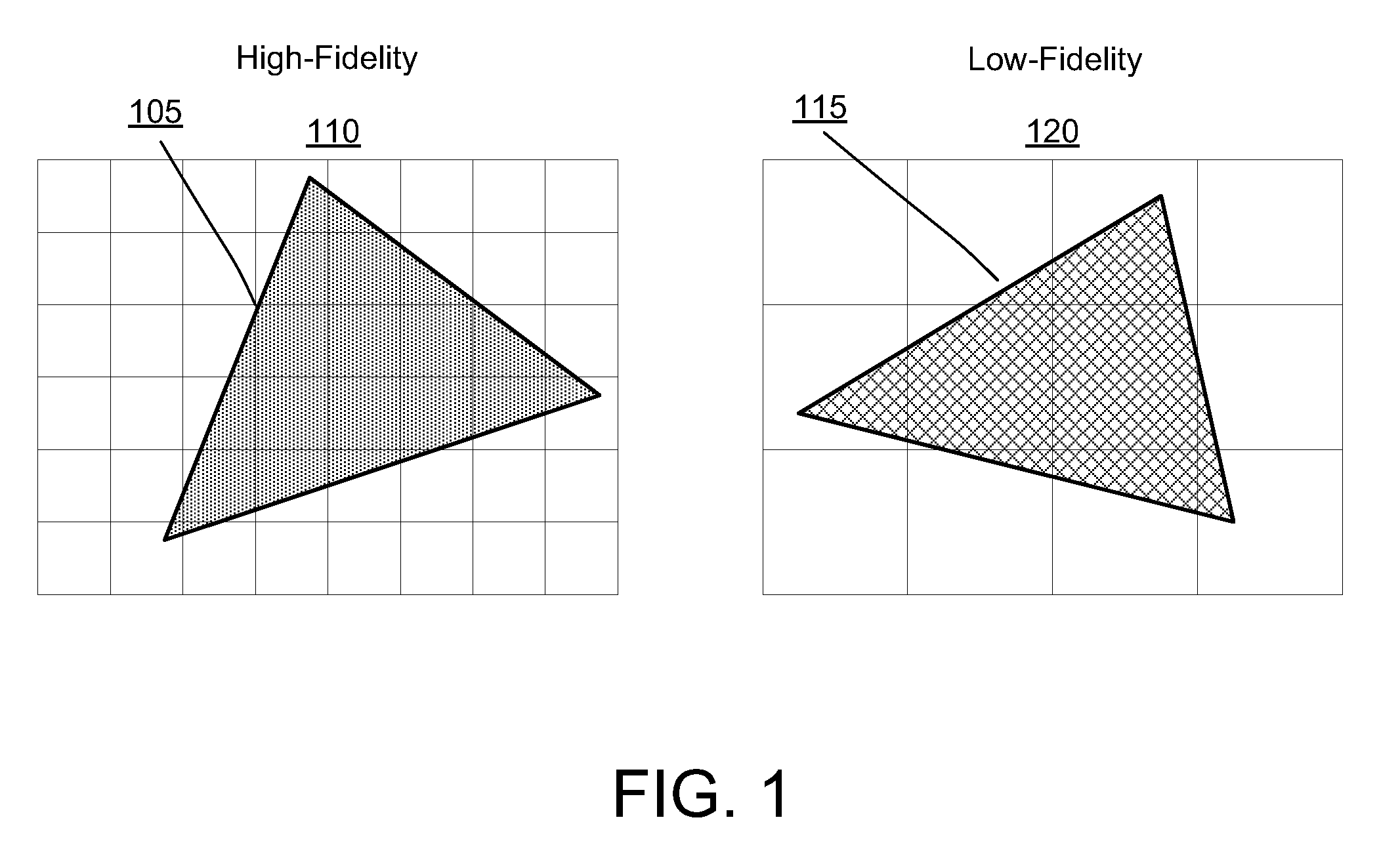
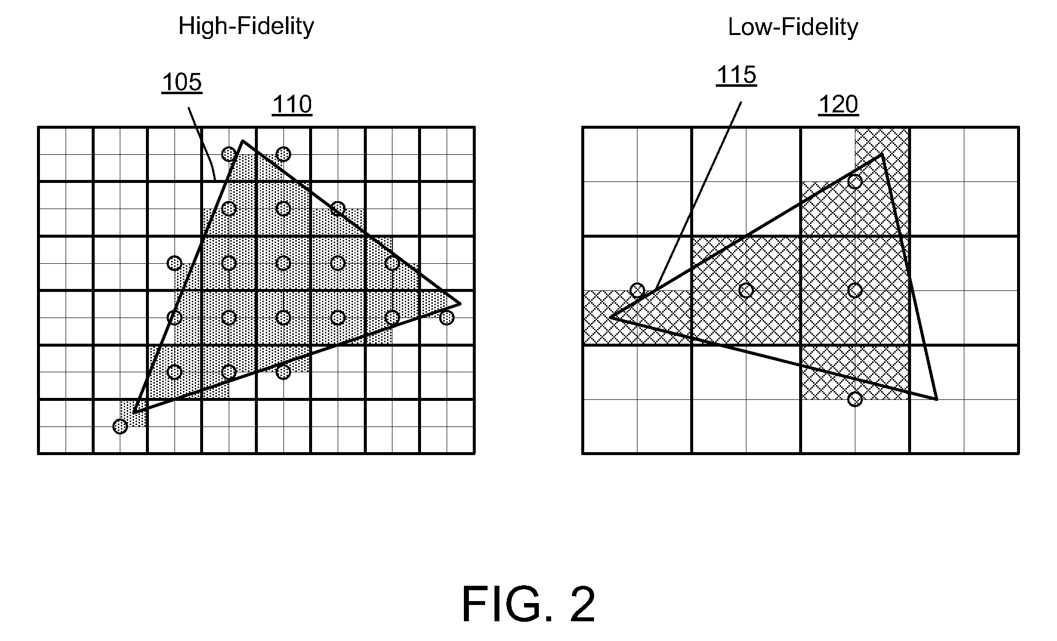
[0021]FIG. 1 illustrates an exemplary pixel rendering of a set of polygons. A “high-fidelity” polygon 105 is shown as it overlays a portion of a pixel structure 110. A “low-fidelity” polygon 115 is shown as it overlays a portion of a pixel structure 120, rendered at lower fidelity than the “high-fidelity” polygon 105. In some embodiments, pixels in the pixel structures rendering lower fidelity polygons may be larger than pixels in the pixel structures rendering higher fidelity polygons. As illustrated, the pixels shown in the pixel structure 120 are twice as large both horizontally and vertically than the pixels shown in t...


PUM


Abstract

Rendering of objects techniques can include a method, a system, and a graphics device. The method can include receiving data for one or more objects. The data for each object can include a fidelity code, wherein the fidelity code indicates object fidelity level. The method further can include computing pixels touched by each received object based on a pixel grid associated with the fidelity code of the object. The method further can include providing pixel data for objects having fidelity code indicating a lower fidelity object.

Description

BACKGROUND OF THE INVENTION[0001]The present disclosure relates generally to the field of computer generated imagery or graphics. Computer generated imagery is utilized in various applications including cinematic applications, video game applications, and training applications such as flight simulator applications. Generally, increased fidelity in both scene density and screen resolution is desirable in computer generated imagery applications. In addition, more realistic atmospheric and weather effects are desired.[0002]Certain computer generated applications, such as, interactive computer graphics applications, rely on a three dimensional (3D) digital database to represent the virtual environment. In general, the designers of that environment exploit the capabilities of the target graphics platform which processes data to produce the 3D environment. To achieve as much fidelity as possible, the designers often populate the database with as much scene content as the target platform e...

Claims


Application Information

Patent Timeline
Patent Type & Authority Patents(United States)
IPC IPC(8): G06T1/60G06T15/00
CPCG06T15/005G06T15/00G06T2210/36G06T1/60G06T11/40G06T15/40
Inventor GARDINER, HAROLD, D.
Owner ROCKWELL COLLINS INC
Why Eureka
Try Eureka