Supercharge Your Innovation With Domain-Expert AI Agents!

Bushing assembly for draw-out circuit breaker

a circuit breaker and assembly technology, applied in the direction of substation/switching arrangement casings, switchgear with a retractable carriage, furniture parts, etc., can solve the problems of difficult mechanical assistance for electricians to move the circuit breaker to electrically connect and disconnect it from the switchboard, the contact pressure of the primary disconnect contacts becomes extremely difficult, and the weight and bulk of the circuit breaker is difficult to handl

Active Publication Date: 2014-03-25
ABB (SCHWEIZ) AG
View PDF14 Cites 6 Cited by
  • Summary
  • Abstract
  • Description
  • Claims
  • Application Information

AI Technical Summary

Benefits of technology

The present invention provides a rear panel for a draw-out circuit breaker assembly that includes a metal plate with holes for a top and bottom, and two identical bushing blocks with conductors. The engagement edge of the top bushing block intermeshes with the engagement edge of the bottom bushing block to restrict relative movement. The bushing blocks extend through the holes in the metal plate. This design provides improved strength and stability for the circuit breaker assembly.

Problems solved by technology

In high current applications, circuit breakers are typically quite large, which makes it difficult to move the circuit breaker to electrically connect and disconnect it from a switchboard without mechanical assistance.
Not only does the weight and bulk of the circuit breaker become difficult for the electrician to handle, but, as the current ratings increase, the contact pressures of the primary disconnect contacts become extremely difficult, if not impossible to overcome.
Though the previous back panel / bushing design is functional, drawbacks persist.

Method used


Image

  • Bushing assembly for draw-out circuit breaker
  • Bushing assembly for draw-out circuit breaker
  • Bushing assembly for draw-out circuit breaker

Examples


Embodiment Construction

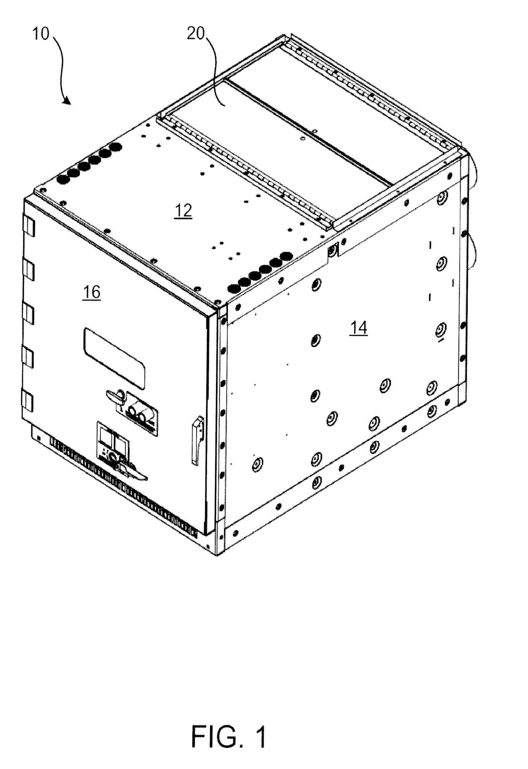
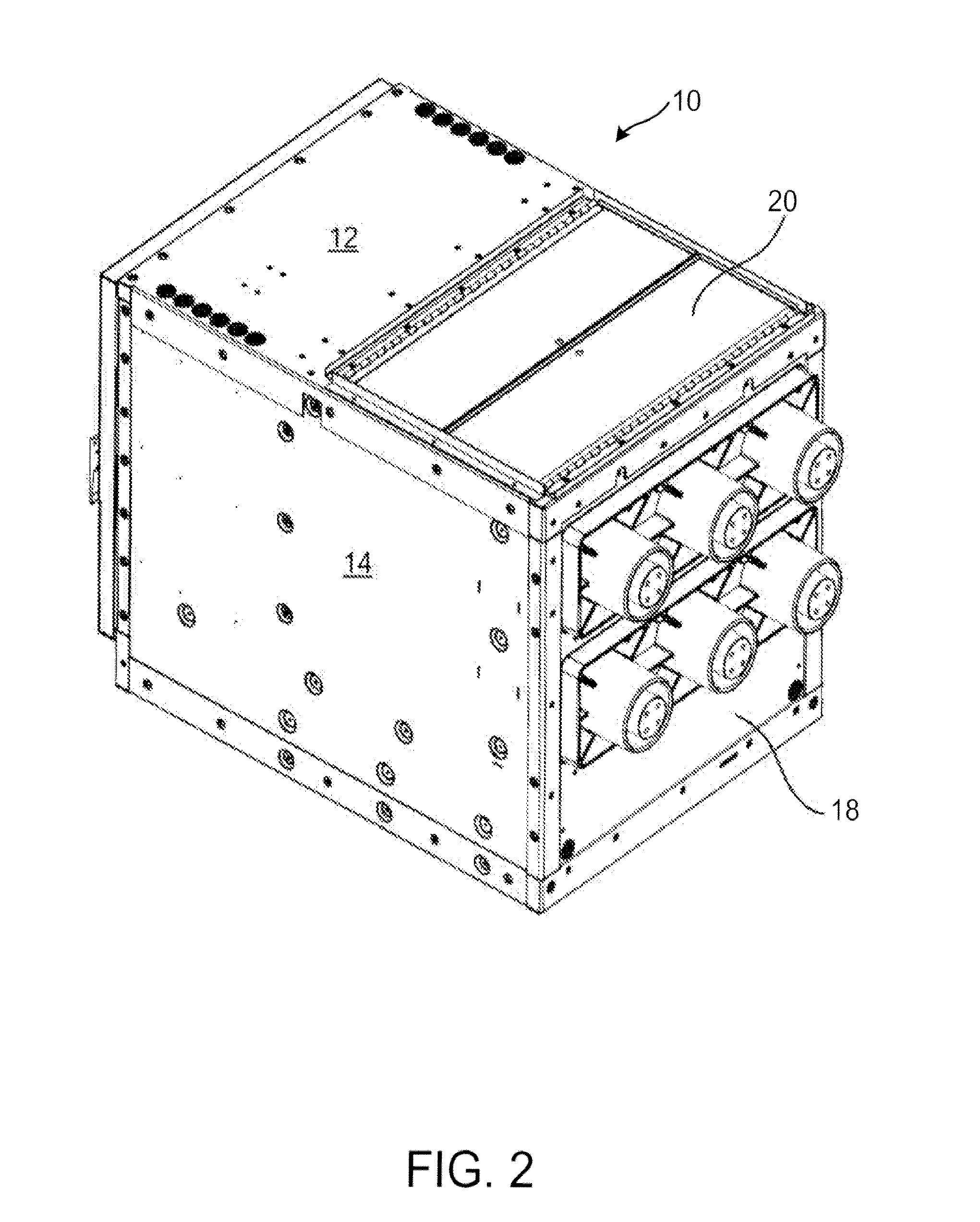
[0028]With reference now to FIGS. 1-4, a pull-out circuit breaker assembly is shown and generally indicated by the numeral 10. Circuit breaker assembly 10 is generally rectangular in shape and includes a top panel 12, bottom panel (not shown), side panels 14, a front panel 16 and a rear panel 18. Top panel 12 includes hinged flaps 20 that, in the case of an accidental arcing, allow gas and / or plasma to escape upwardly.

[0029]With reference now to FIGS. 5-8 it can be seen that breaker assembly 10 is internally separated into a front chamber 22 and a rear chamber 24 by an interior wall 26. Various monitoring and / or control electronics 28 are mounted on interior wall 26 facing the front chamber 22. Front chamber 22 is accessible through the hinged front panel 16.

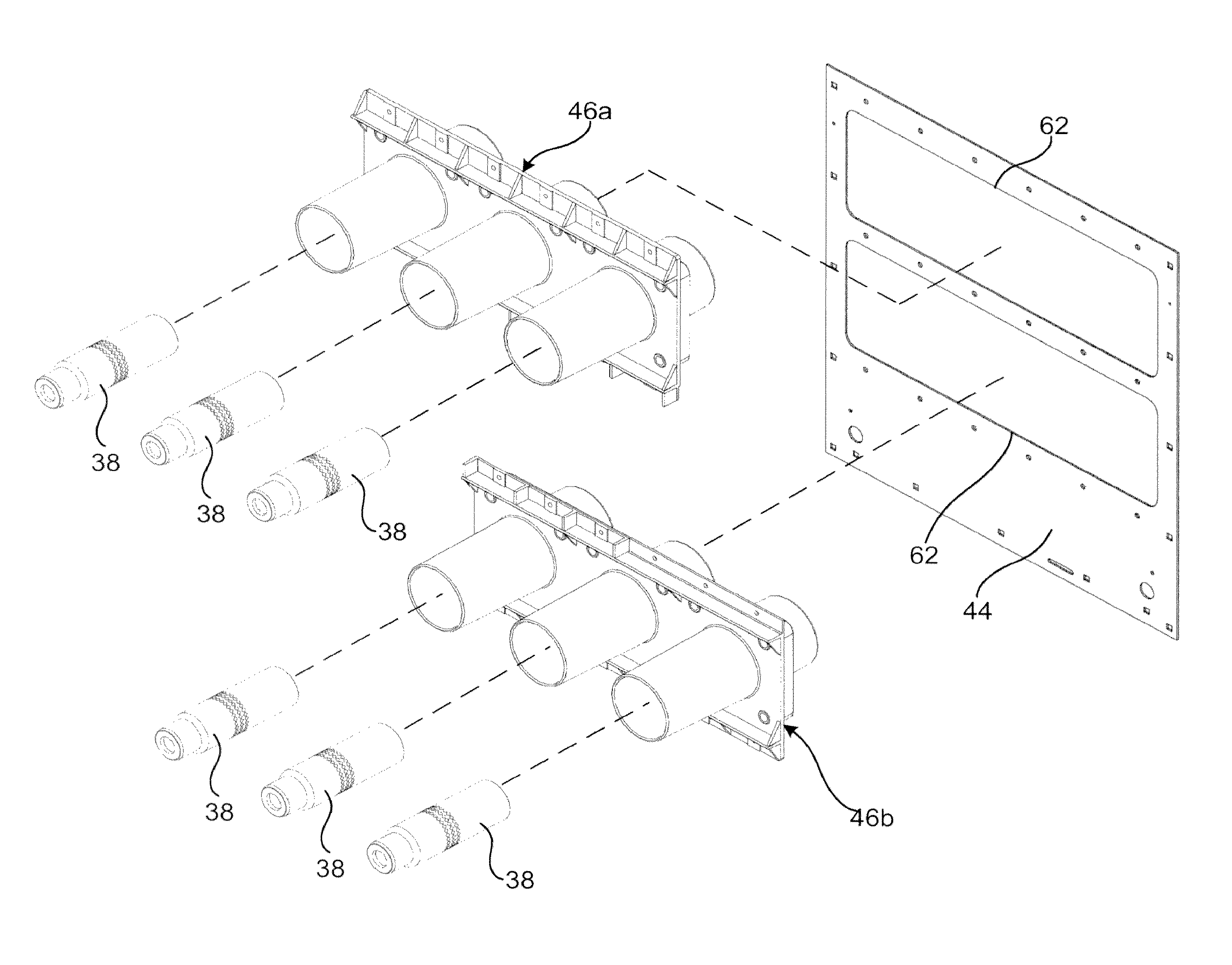
[0030]Three individual circuit breaker vacuum interrupter pole assemblies 30 are located within rear chamber 24. As is known in the art, breaker poles 30 each include a top electrical disconnect 32 and a bottom electrical discon...


PUM


Abstract

A rear panel for a draw-out circuit breaker includes a metal plate having a pair of rectangular cutouts. Two bushing blocks are joined together and at least partially extend through the cutouts. Each molded bushing block includes three bushings, each of which carry an electrical conductor that is over-molded therein.

Description

BACKGROUND[0001]In high current applications, circuit breakers are typically quite large, which makes it difficult to move the circuit breaker to electrically connect and disconnect it from a switchboard without mechanical assistance. Not only does the weight and bulk of the circuit breaker become difficult for the electrician to handle, but, as the current ratings increase, the contact pressures of the primary disconnect contacts become extremely difficult, if not impossible to overcome. To overcome these problems, so-called “draw-out” assemblies are used to support the circuit breaker and provide mechanical assistance to overcome the contact pressures of the disconnect contacts.[0002]Draw-out apparatus are generally designed to support the electrical device for racking movement between an extended position and an engaged position where the load current carrying primary disconnects of the device are fully engaged. As is well known in the art, three-phase draw-out circuit breakers i...

Claims


Application Information

Patent Timeline
Patent Type & Authority Patents(United States)
IPC IPC(8): H02B11/12H02B1/20
CPCH02B11/04
Inventor PATTEN, ROBERT A.KARNBACH, ROBERT S.MCNAMARA, THOMAS P.
Owner ABB (SCHWEIZ) AG
Features
  • R&D
  • Intellectual Property
  • Life Sciences
  • Materials
  • Tech Scout
  • Unparalleled Data Quality
  • Higher Quality Content
  • 60% Fewer Hallucinations
Learn More