
Tactical illuminator

a technology of illuminators and illuminators, which is applied in the field of illuminators, can solve the problems of reflecting off other objects, blinding the user or their team members, and tedious tasks

Active Publication Date: 2014-04-01
AOB PROD CO
View PDF42 Cites 51 Cited by
  • Summary
  • Abstract
  • Description
  • Claims
  • Application Information

AI Technical Summary

Problems solved by technology

When a user is getting into a tactical situation, e.g. a law enforcement SWAT team about to raid a methamphetamine lab or an apartment complex, a bright light may give away the users position and may reflect off other objects and blind the user or their team members.
While the above three uses of light are needed by tactical users of a weapon, the user must remove one illuminator for another, which is a tedious task.

Method used


Image

  • Tactical illuminator
  • Tactical illuminator
  • Tactical illuminator

Examples


Embodiment Construction

[0019]In the following description, like reference characters designate like or corresponding parts throughout the several views. Also in the following description, it is to be understood that such terms as “forward,”“rearward,”“front,”“back,”“right,”“left,”“upwardly,”“downwardly,” and the like are words of convenience and are not to be construed as limiting terms.

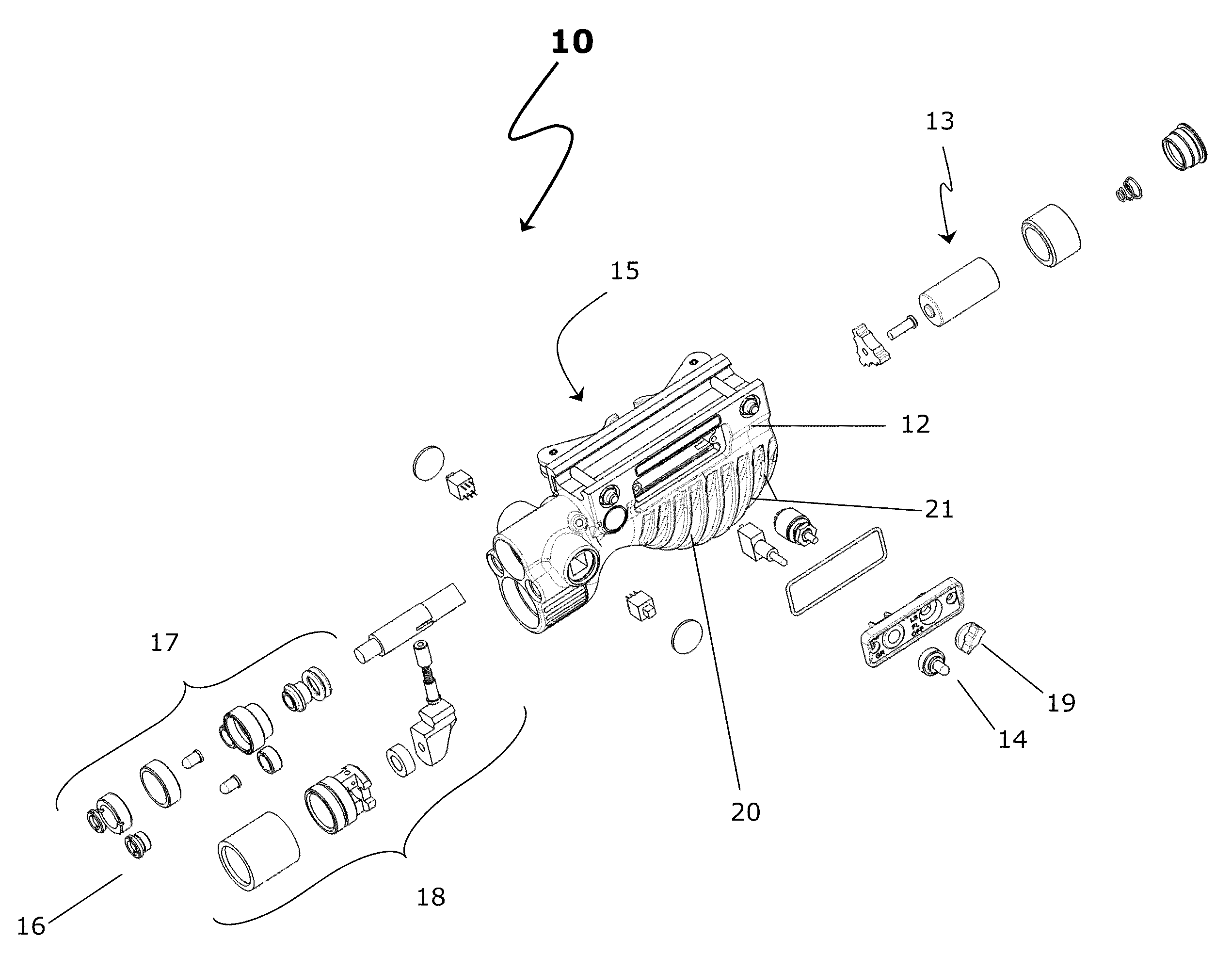
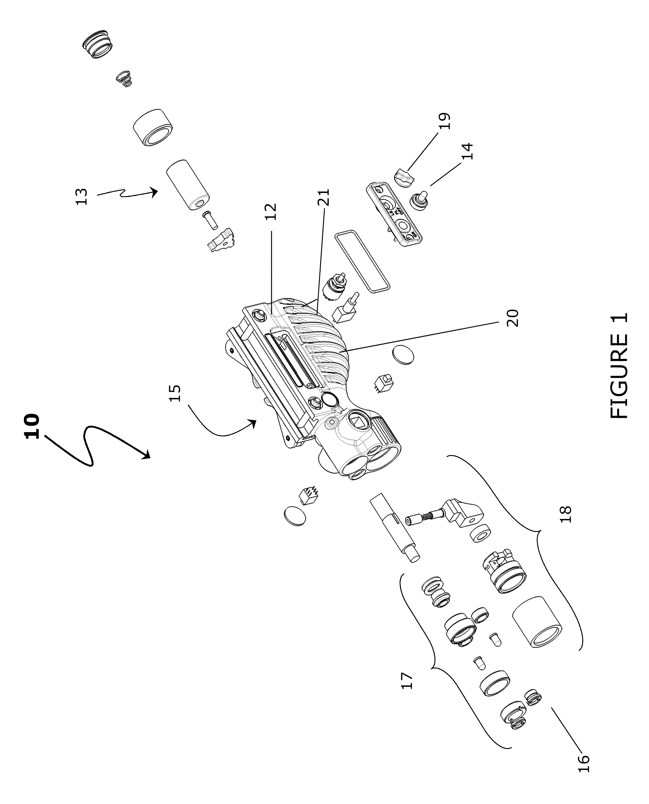
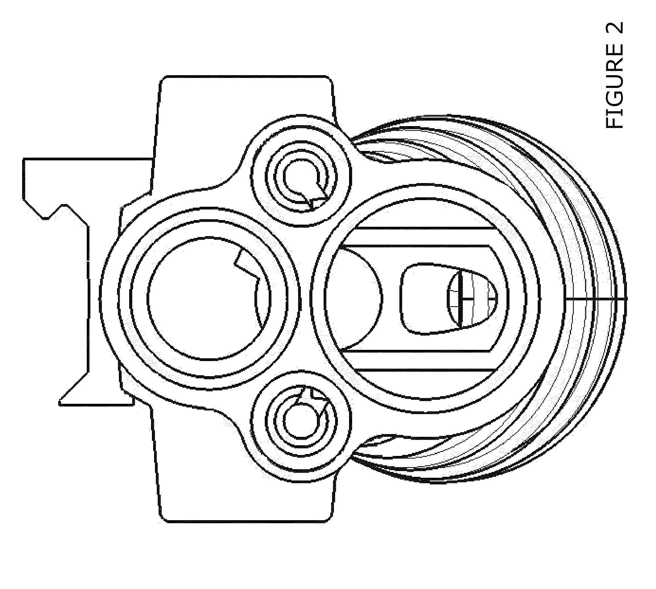
[0020]The present invention preferably provides a tactical illuminator having no vertical foregrip. A tactical illuminator of the present invention includes an integrated illuminator system including a horizontally-oriented body forming a foregrip, a power source, a multi-position rotary switch, a toggle switch, a depressible switch, an attachment mechanism, navigation lights, an aiming laser, and a main illuminator, wherein the horizontally-oriented body further includes an ergonimically shaped grip region constructed and configured to fit within the palm of a human hand. Advantageously, this body functions equally well f...


PUM


Abstract

A tactical illuminator having an integrated illuminator system including a horizontally-oriented foregrip, a power source, a multi-position rotary selector switch, a toggle switch, a depressible switch, an attachment mechanism, navigation lights, an aiming laser, and a main illuminator.

Description

CROSS-REFERENCE TO RELATED APPLICATIONS[0001]This application claims the benefit of one or more prior-filed, applications: it claims priority from U.S. Provisional Patent Application No. 61 / 068899 filed Mar. 11, 2008 and is a continuation-in-part of U.S. Non-Provisional Patent Application No. 12 / 381,386, filed on Mar. 11, 2009 now U.S. Pat. No. 8,117,782.BACKGROUND OF THE INVENTION[0002]1. Field of the Invention[0003]The present invention relates generally to illuminators. Further, the present invention relates to weapon-mounted illuminators.[0004]2. Description of the Prior Art[0005]Generally while using a weapon, such as a rifle, for tactical purposes, it is desirable to illuminate an area for visibility reasons. Additionally, it is desirable to have an aiming device on the rifle to assist with targeting. Tactical use implies providing a temporary advantage to the user of the weapon. And tactical by itself, in this context, generally refers to law enforcement, military, and other ...

Claims


Application Information

Patent Timeline
Patent Type & Authority Patents(United States)
IPC IPC(8): F41G1/35
CPCF41G1/36F41G1/35F41G11/003F41C23/16F41C23/22
Inventor GROSS, BARBARA R.HOLMES, DANNY J.
Owner AOB PROD CO
Learn More