
Method of electrically connecting cell terminals in a battery pack

a cell terminal and battery pack technology, applied in the direction of batteries, cell components, battery/fuel cell control arrangements, etc., can solve the problems of battery pack thermal cooling efficiency poor, 9% loss of total capacity, and substantial loss of overall energy capacity

Active Publication Date: 2014-04-01
ATIEVA USA INC
View PDF1 Cites 5 Cited by
  • Summary
  • Abstract
  • Description
  • Claims
  • Application Information

AI Technical Summary

Benefits of technology

The present invention is about a new design for battery packs that use a large number of small battery cells. These cells are interconnected using a multi-cell battery system that has several advantages over traditional battery packs. First, using a large number of small cells reduces the impact of cell failure on the overall energy capacity of the battery pack. Second, the design improves thermal cooling efficiency. Third, the design reduces the complexity of interconnecting cells using conventional interconnection techniques. The invention also includes a layout for the physical arrangement of the battery cells in a module and a frame for holding cells in a module. The design parameters for the battery pack are also provided. Overall, the invention provides a low part-count battery pack that economically and reliably interconnects a large number of small battery cells.

Problems solved by technology

First, if one of the cells fails, a substantial percentage of the overall energy capacity would be lost.
For example, for a pack using 11 cells, a single cell failure would result in a 9% loss of total capacity.
Second, such a battery pack has poor thermal cooling efficiency.
Battery cells degrade when subject to elevated temperatures.
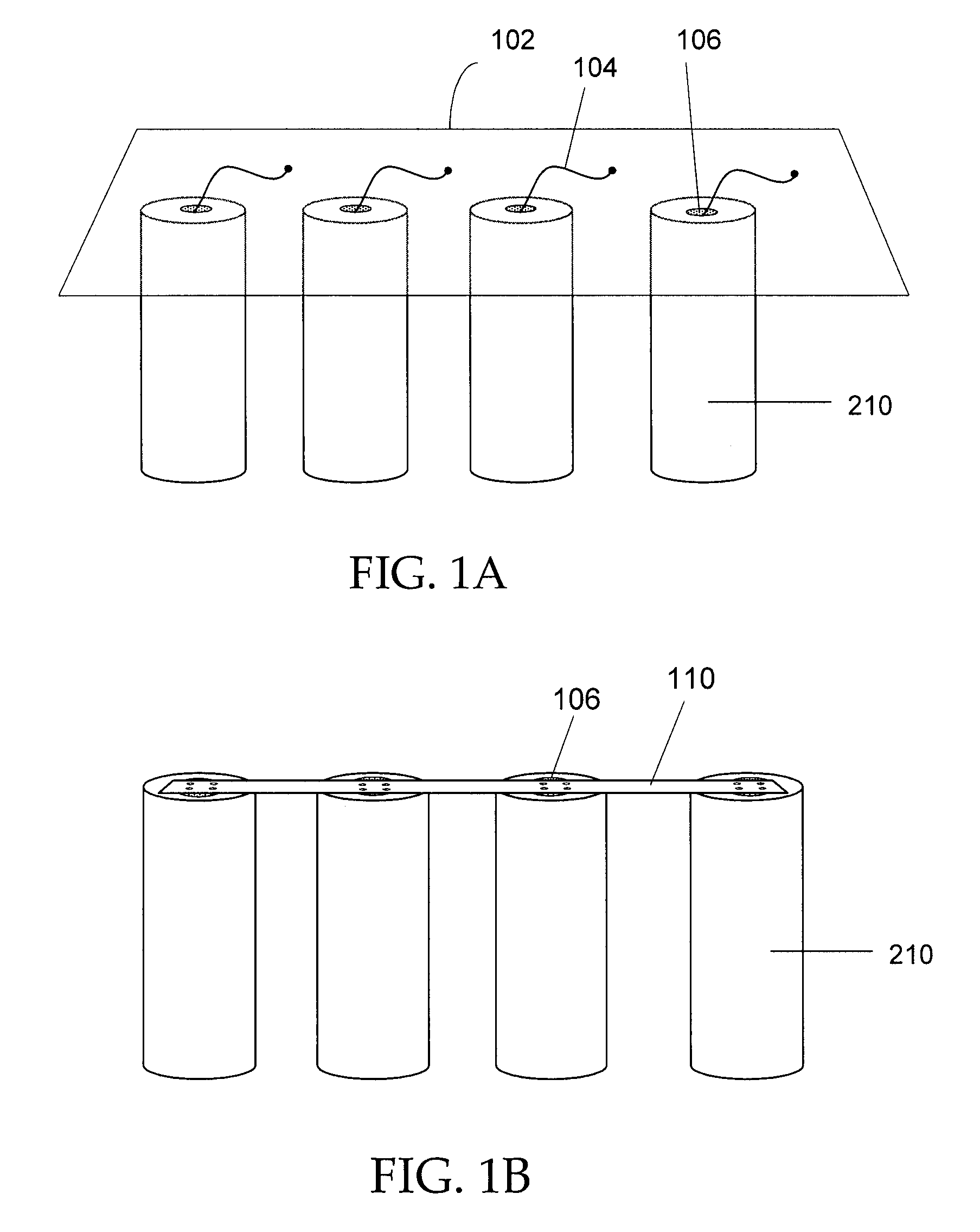
Unfortunately, such battery packs tend to be tremendously expensive, due in part to the large number of pack components and the complexity involved in interconnecting such a large number of cells 210 using conventional interconnection techniques (e.g., conducting wires 104 coupled from respective cell terminals 106 to a metal plate 102 as shown in FIG. 1A, or a metal strip 110 welded to cell terminals 106 as shown in FIG. 1B).
Moreover, conventional cell interconnections (welded wires or strips) are susceptible to failure when the cells dislocate slightly during operation, for example, due to vibration within a moving vehicle.

Method used


Image

  • Method of electrically connecting cell terminals in a battery pack
  • Method of electrically connecting cell terminals in a battery pack
  • Method of electrically connecting cell terminals in a battery pack

Examples


Embodiment Construction

[0017]A low part-count battery pack that economically and reliably interconnects a large number of small form-factor battery cells is disclosed in various embodiments.

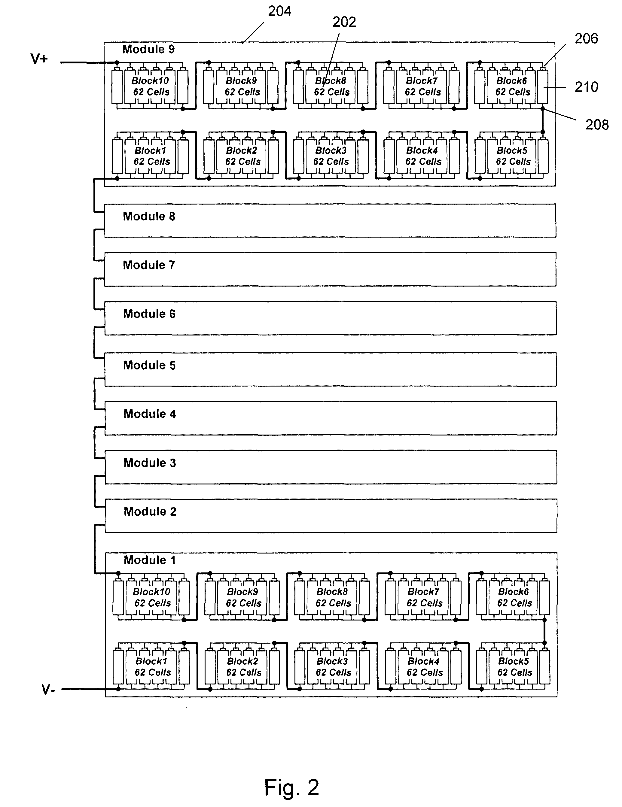
[0018]FIG. 2 shows one embodiment of a battery pack using a large number of small battery cells. In this embodiment, cells 210 are grouped into a number of blocks 202; blocks are in turn grouped into modules 204. In the example shown in FIG. 2, each pack comprises nine (9) modules; each module comprises ten (10) blocks; and each block comprises sixty two (62) cells. Therefore, there are a total number of five thousand five hundred and eighty (5580) cells in a pack. Each cell 210 has a positive and a negative terminal, called a cathode 206 and an anode 208, respectively. In this embodiment, the cells in each block are electrically connected in parallel, i.e., the cathodes are connected together, and the anodes are connected together. The blocks in each module are connected in series, i.e., the cathode of the first block...


PUM


Abstract

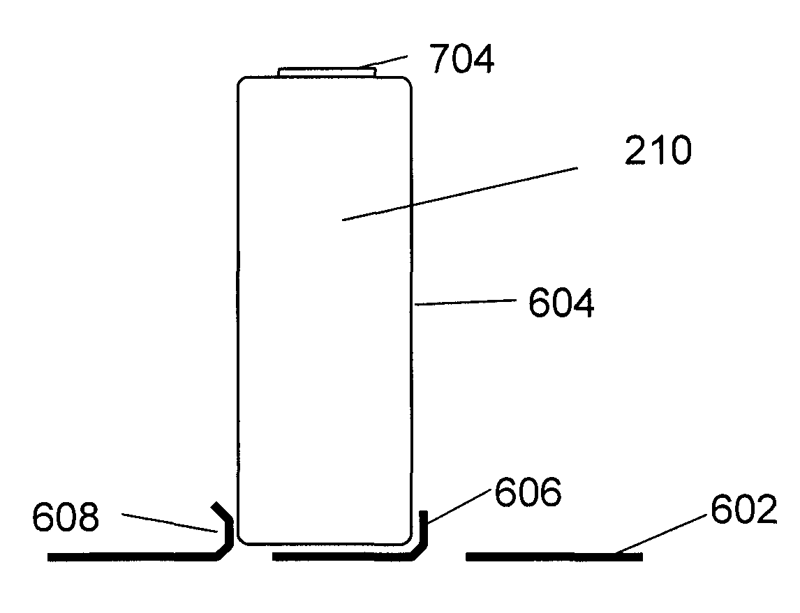
A battery pack that economically and reliably interconnects a large number of small form-factor battery cells. A conducting plate with a plurality of sets of tabs protruding from a flat surface of the conducting plate is used to connect electrical terminals of a plurality of battery cells. Each set of tabs is disposed about and exerts a spring force to a respective battery cell, thus mechanically securing and electrically connecting the conducting plate to the cell.

Description

PRIORITY AND CROSS-REFERENCE TO RELATED APPLICATIONS[0001]This application is a divisional application of U.S. patent application Ser. No. 12 / 372,656 filed Feb. 17, 2009, and hereby incorporates by reference, U.S. Provisional Application No. 61 / 029,300, filed on Feb. 15, 2008.FIELD OF THE INVENTION[0002]The present invention relates to multi-cell battery systems.BACKGROUND[0003]Battery packs have been used in automotive and industrial applications for many years. Traditionally, these battery packs use a relatively small number of large battery cells, typically lead-acid type battery cells. A battery pack design that uses a small number of large battery cells has several disadvantages. First, if one of the cells fails, a substantial percentage of the overall energy capacity would be lost. For example, for a pack using 11 cells, a single cell failure would result in a 9% loss of total capacity. Second, such a battery pack has poor thermal cooling efficiency. The cooling efficiency of ...

Claims


Application Information

Patent Timeline
IPC IPC(8): H01M4/02H01M50/213H01M50/505H01M50/509H01M50/522
CPCY02T10/7061B60L3/0046B60L11/1864H01M2/206Y02T10/7005B60L2240/545Y02E60/12H01M6/425B60L2240/547B60L11/1877B60L2240/549H01M2/1077B60L11/1874H01M2220/20B60L58/21B60L58/26B60L50/66B60L58/18Y02T10/70H01M50/522H01M50/213H01M50/509H01M50/505Y02E60/10
Inventor LIN, SHEAU-PYNG
Owner ATIEVA USA INC
Learn More