Image processing apparatus, control method thereof and computer program

a control method and image processing technology, applied in the field of image processing apparatus, a control method thereof and a computer program, can solve the problems of difficult to visualize only difficult to visualize the three-dimensional blood flow in the fundus blood vessel,

Inactive Publication Date: 2014-04-01
CANON KK
View PDF30 Cites 6 Cited by
  • Summary
  • Abstract
  • Description
  • Claims
  • Application Information

AI Technical Summary

Benefits of technology

[0009]Accordingly, the present invention allows improvement over the problems encountered in the prior art described above and to provide the technology to visualize the three-dimensional flow in the blood vessel or three-dimensional distribution of the achromoderma from the retinal volume data.

Problems solved by technology

The following problems exist in the visualization of 3D flow of the blood in the fundus blood vessel by using the retinal volume data.
In the method according to the specification of Japanese Patent Laid Open No. 2008-006274, the blood vessel area in the luminance value histogram of OCT does not present the peak, so it is difficult to visualize the three-dimensional blood flow in the fundus blood vessel.
That is, the area where the fundus blood vessel 202 runs has low contrast, and even if the transfer function is set manually based on the luminance value, it is difficult to visualize only the fundus blood vessel.

Method used


Image

  • Image processing apparatus, control method thereof and computer program
  • Image processing apparatus, control method thereof and computer program
  • Image processing apparatus, control method thereof and computer program

Examples


first embodiment

Visualization of a Blood Vessel Blood Vessel

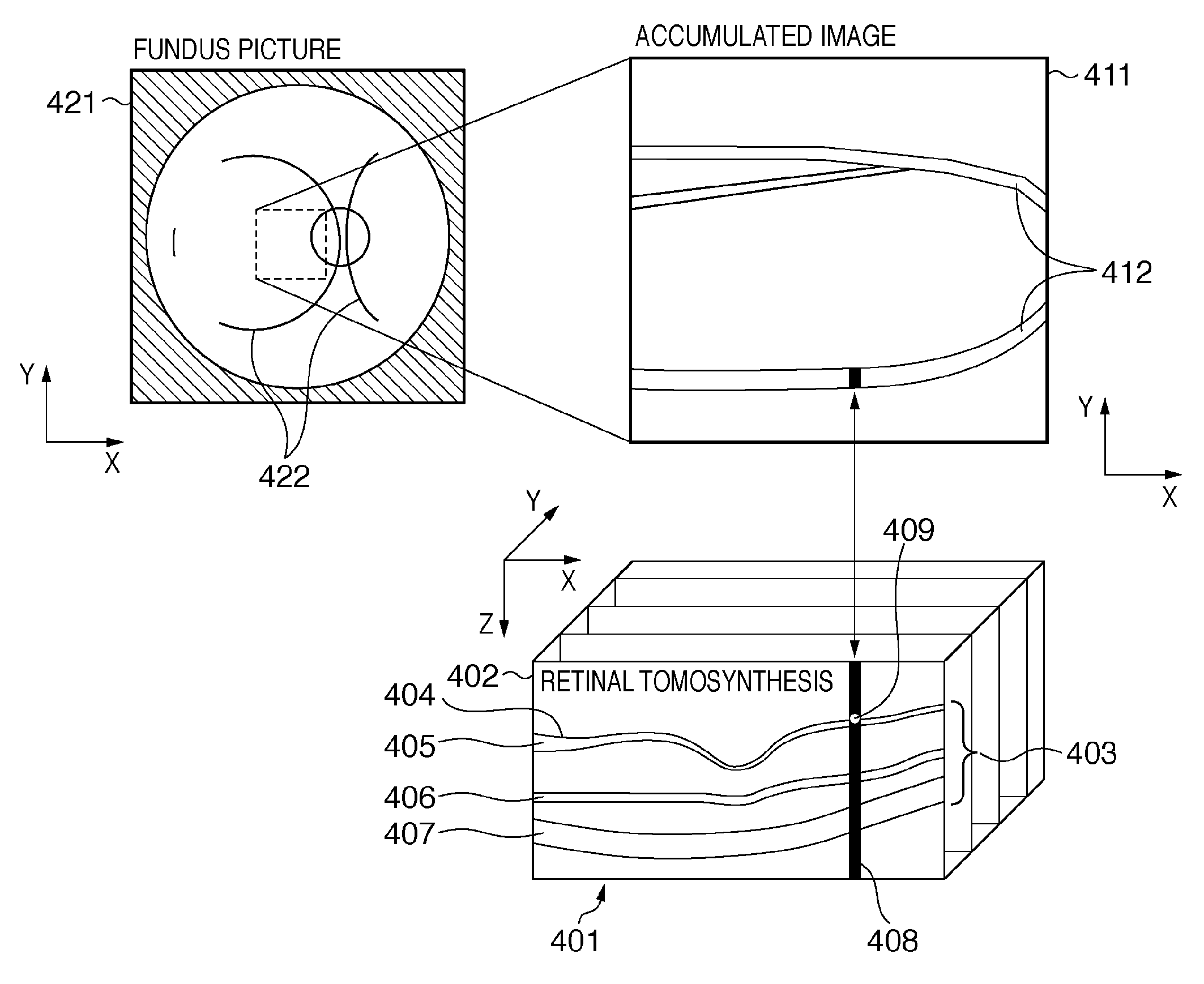
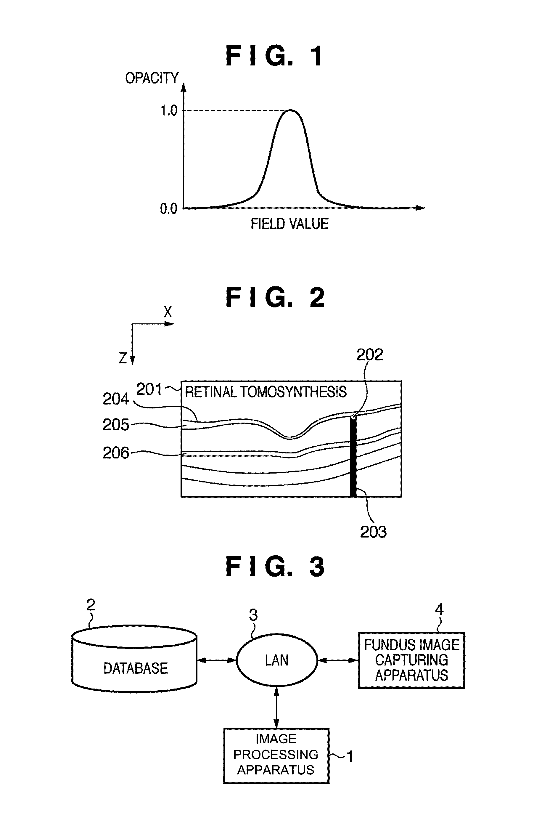
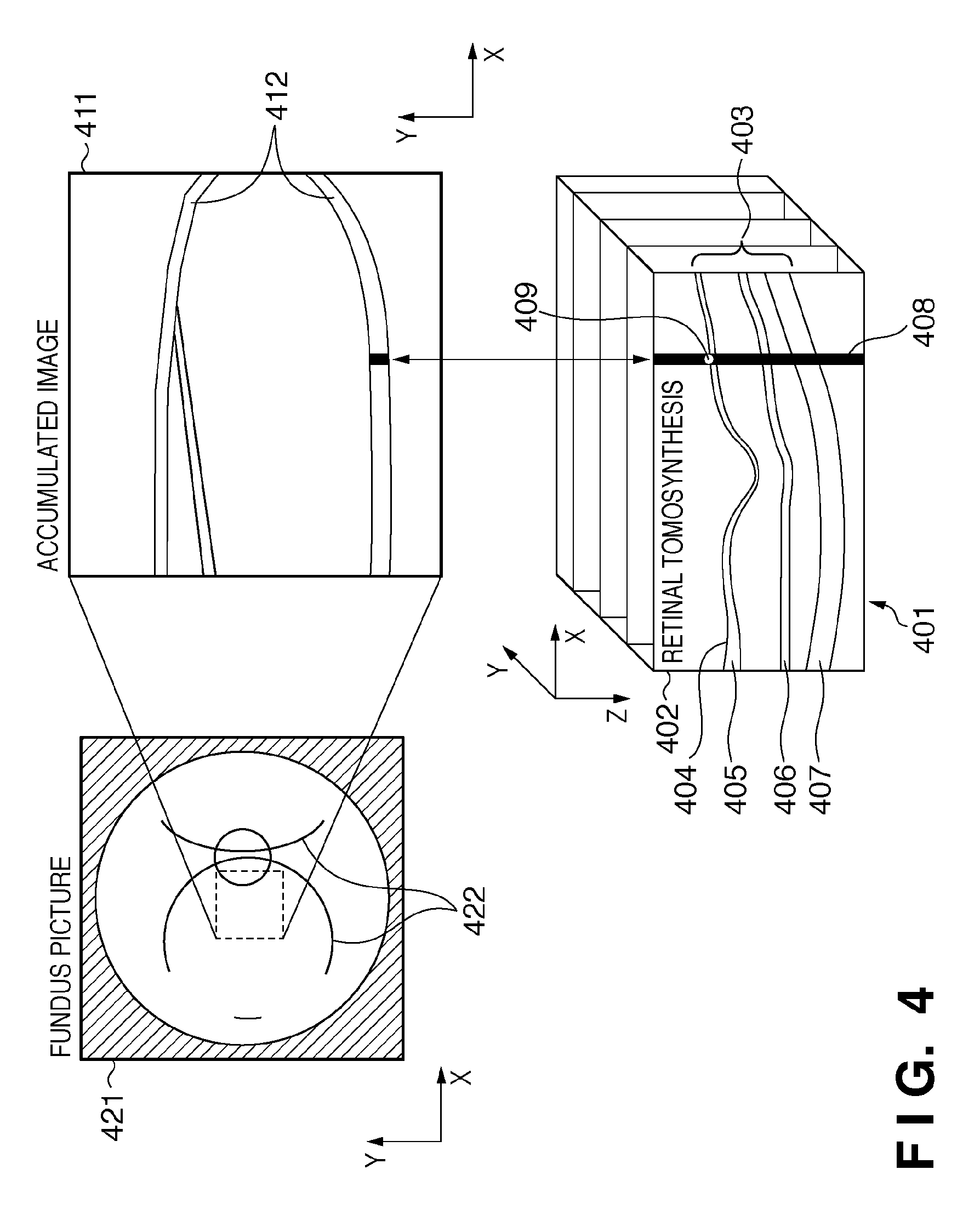
[0025]FIG. 3 is a chart showing one example of the structure of an image processing apparatus according to the present embodiment. In this embodiment, an image processing apparatus 1 reads out a fundus image from a database 2 through a LAN 3. Alternatively, a memory device such as an FDD, CD-RW drive, MO drive, or ZIP drive, or the like, may be connected to the image processing apparatus 1 and the fundus image may be read out from such a drive. In addition, a medical image or the like may be obtained directly from a fundus image capturing apparatus 4 via the LAN 3. In addition to the fundus image, the database 2 stores patient names or patient data, thickness information of a retina 403, nerve fiber layer 405, outer plexiform layer 406, and the retinal pigment epithelium 407 shown in FIG. 4. FIG. 4 is a chart for explaining the relationship between the fundus picture, retinal volume data and the accumulated image.

[0026]As the fundus image ...

second embodiment

Visualizing the Achromoderma

[0051]In the above first embodiment, the three-dimensional rendering of the fundus blood vessel is visualized by extracting the blood vessel area and the layer boundary from the fundus image, and by volume-rendering the blood vessel using the opacity calculated from the distance from the layer boundary and the luminance value of the retinal volume data. On the other hand, in the second embodiment, not the blood vessel but the achromoderma is visualized as the discriminative lesion of the fundus oculi.

[0052]The structure of the image processing apparatus and the apparatus connected thereto is same as that of the first embodiment as shown in FIG. 2. However, the functional block of the image processing apparatus according to the present embodiment is configured by adding an achromoderema area extraction unit 1001 to the functional block according to the first embodiment as shown in FIG. 10.

[0053]The description of this embodiment will primarily explain the ...

third embodiment

[0062]The image processing apparatus and the apparatus connected thereto are same as those of the first embodiment, as shown in FIG. 2. The basic structure of the computer for realizing the function of the respective units is also same as that of the first embodiment, as shown in FIG. 12.

[0063]The distance transfer function setting unit 505 in the first and second embodiments comprises an average thickness of the retina obtaining unit 701, function parameter input unit 702, a shadow area extraction unit 703, the achromoderma center searching unit 704 and a layer boundary obtaining unit 705, as shown in FIG. 7. The distance transfer function is set by using the shadowed area extraction unit 703 in the first embodiment and by using the achromoderma center searching unit 704 in the second embodiment. In the present embodiment, the method of setting the distance transfer function by using one of the average thickness of the retina obtaining unit 701, the function parameter input unit 70...


PUM


Abstract

One aspect of embodiments of the present invention relates to an image processing apparatus which specifies one of boundary positions of retina layers in a fundus image showing a retina tomosynthesis, sets a distance transfer function for converting the distance from the specified boundary position to a parameter expressing opacity such that the peak position of the opacity is set to a predetermined position in the retina, sets a luminance transfer function for converting a luminance value of the fundus image to the parameter expressing opacity, and generates a translucent display image by calculating the opacity of respective positions of the tomosynthesis using the distance transfer function and the luminance transfer function, and by volume rendering.

Description

TECHNICAL FIELD[0001]The present invention relates generally to an image processing apparatus, a control method thereof and a computer program.BACKGROUND ART[0002]In ophthalmology, a fundus camera has generally been used to capture a picture of the fundus of the eye. In recent years, as an optical coherence tomography (hereinafter “OCT”) has appeared, capturing tomosynthesis of a retina has become possible. As a result of this, new knowledge in ophthalmology that the retina forms a layer structure and that the layer structure is destroyed as disease progresses has been discovered. At present, as disclosed in the specification of Japanese Patent Laid Open No. 2008-073099, the layer structure is extracted from the retinal volume data, which is reconstructed from plural tomosynthesis of the captured retina, and the information thereof is utilized in the diagnosis of eye disease. Hereinafter, the fundus picture and retinal volume data will be referred to the fundus image.[0003]In the ex...

Claims


Application Information

Patent Timeline
Patent Type & Authority Patents(United States)
IPC IPC(8): G06K9/00
CPCA61B3/102G06T7/0081G06T2207/10101G06T2207/30041G06T2207/30101G06T7/11A61B3/12
Inventor TAKAMA, YASUFUMI
Owner CANON KK
Why Eureka
Try Eureka