Part modeled by parallel geodesic curves

a technology parts, applied in the field of computer programs and systems, can solve the problem of even more complicated computation of parallel geodesic curves

Active Publication Date: 2014-04-08
DASSAULT SYSTEMES
View PDF4 Cites 73 Cited by
  • Summary
  • Abstract
  • Description
  • Claims
  • Application Information

AI Technical Summary

Problems solved by technology

Computing a parallel geodesic curve is even more complicated.
However, the offset curve in this patent application is not a geodesic parallel curve.

Method used


Image

  • Part modeled by parallel geodesic curves
  • Part modeled by parallel geodesic curves
  • Part modeled by parallel geodesic curves

Examples


Embodiment Construction

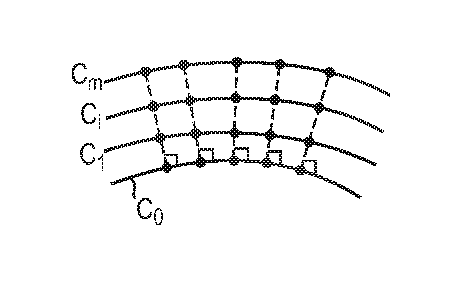
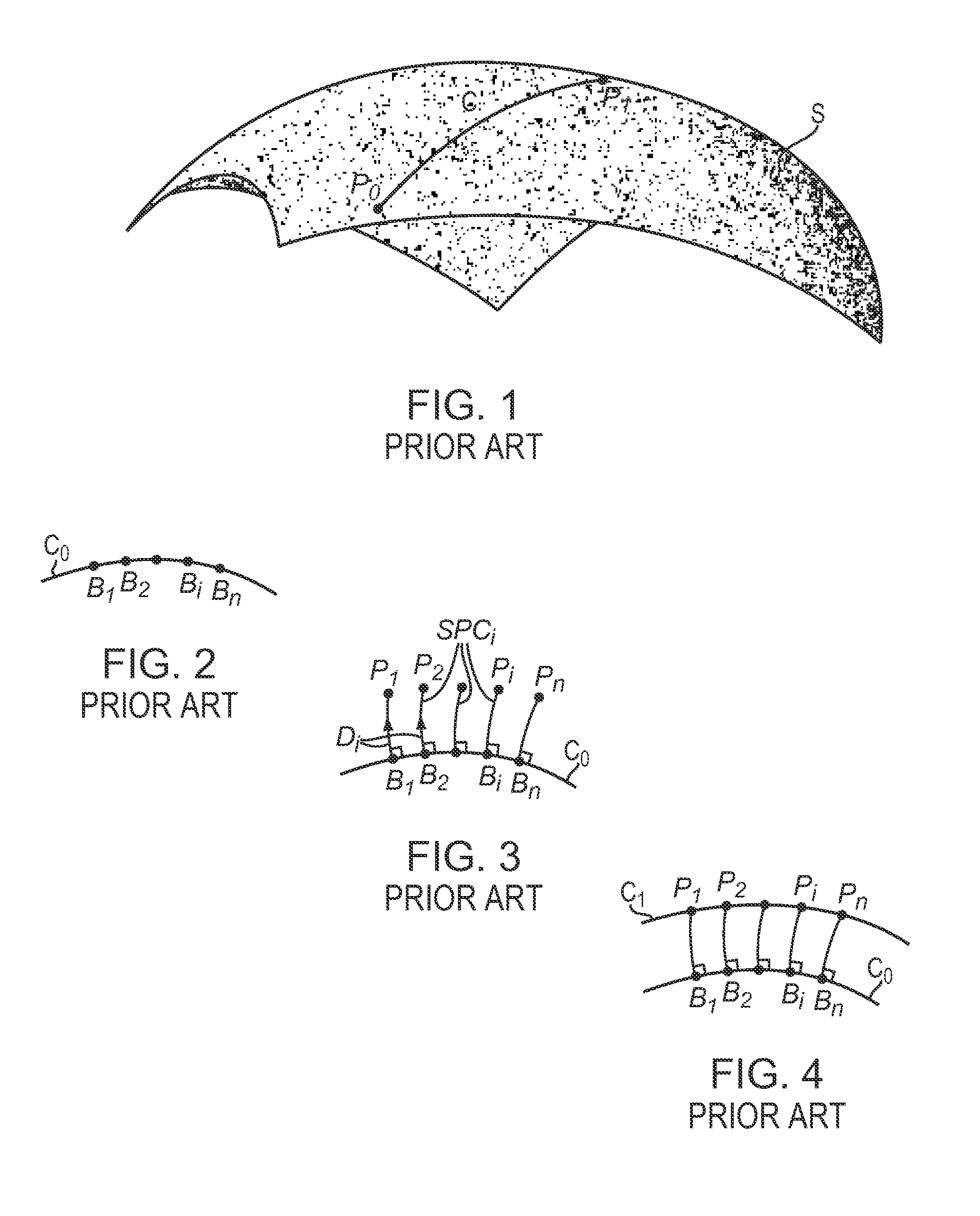
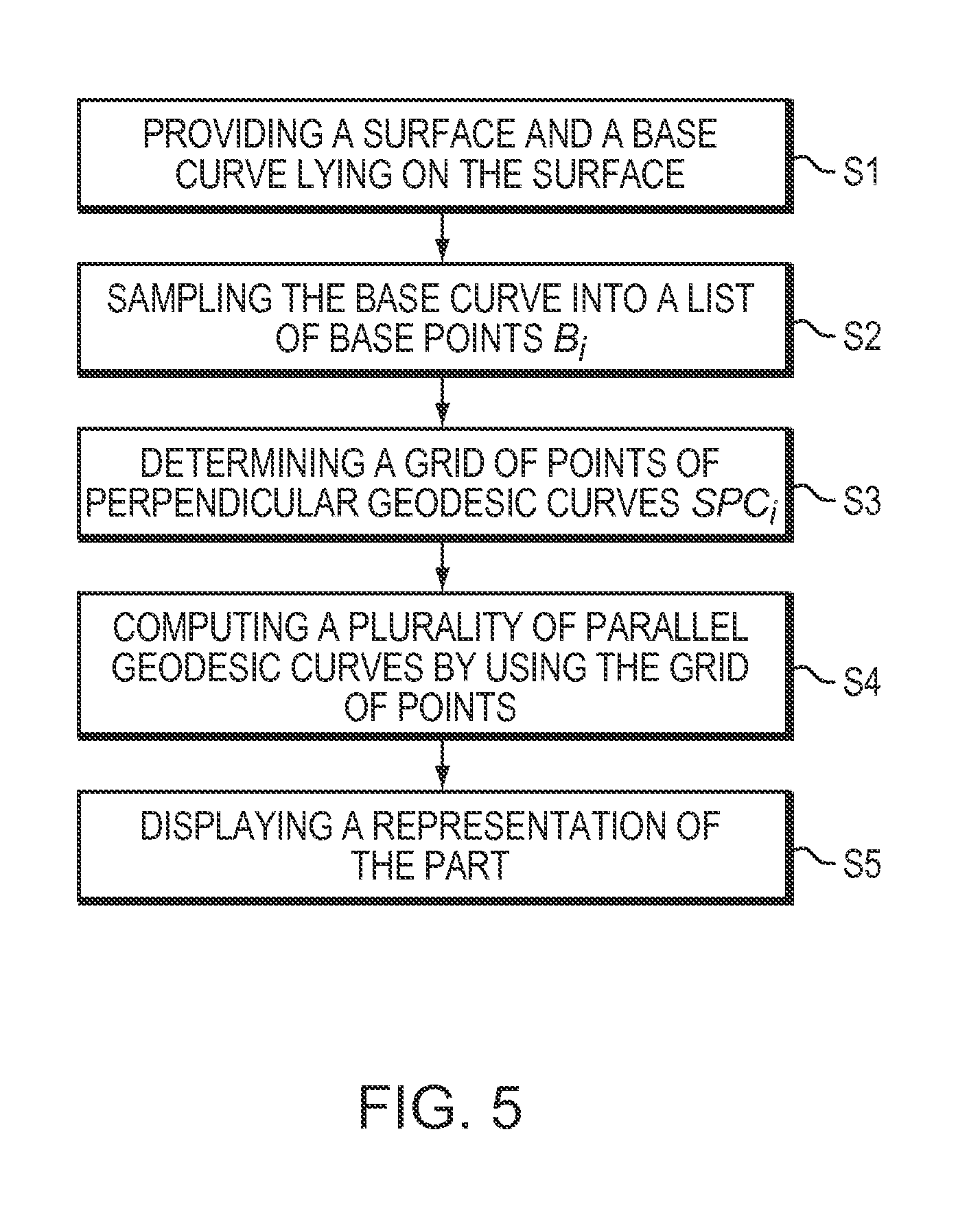
[0069]A computer implemented method according to the invention is intended for designing a part. The method comprises a step of providing a surface and a base curve lying on the surface. The method also comprises a step of sampling the base curve into a list of base points. The method also comprises a step of determining a grid of points of perpendicular geodesic curves. The points of the grid each belong to a respective level. Each level of the grid corresponds to a respective geodesic distance to the base curve. Each perpendicular geodesic curve lies on the surface and departs perpendicularly from the base curve at a respective base point. The method then comprises a step of computing a plurality of parallel geodesic curves lying on the surface by using the grid of points. Each parallel geodesic curve corresponds to a respective level. A representation of the part is displayed according to the method. Such a method offers a new way to design a part.

[0070]The method according to th...


PUM


Abstract

The invention provides a computer implemented method for designing a part. The method comprises a step of providing a surface and a base curve lying on the surface. The method also comprises a step of sampling the base curve into a list of base points. The method also comprises a step of determining a grid of points of perpendicular geodesic curves. The points of the grid each belong to a respective level. Each level of the grid corresponds to a respective geodesic distance to the base curve. Each perpendicular geodesic curve lies on the surface and departs perpendicularly from the base curve at a respective base point. The method then comprises a step of computing a plurality of parallel geodesic curves lying on the surface by using the grid of points. Each parallel geodesic curve corresponds to a respective level. A representation of the part is displayed.

Description

RELATED APPLICATION(S)[0001]This application claims priority under 35 U.S.C. §119 or 365 to European, Application No. 10305344.3, filed Apr. 2, 2010.[0002]The entire teachings of the above application(s) are incorporated herein by reference.FIELD OF THE INVENTION[0003]The invention relates to the field of computer programs and systems, and more specifically to a computer implemented method for designing a part.BACKGROUND OF THE INVENTION[0004]Computer-aided techniques are known to include Computer-Aided Design or CAD, which relates to software solutions for authoring product design. Similarly, CAE is an acronym for Computer-Aided Engineering, e.g. it relates to software solutions for simulating the physical behavior of a future product. CAM stands for Computer-Aided Manufacturing and typically includes software solutions for defining manufacturing processes and operations.[0005]A number of systems and programs are offered on the market for the design of objects (or parts) or assembl...

Claims


Application Information

Patent Timeline
Patent Type & Authority Patents(United States)
IPC IPC(8): G06F17/50
CPCG06T17/30G06T19/00
Inventor BERARD, SIMON
Owner DASSAULT SYSTEMES
Why Eureka
Try Eureka