Pop-top can opener

a pop-top can and opener technology, applied in the field of can openers, can solve the problem that none of the openers provides for the normal flow of liquid contents, and achieve the effect of emptied faster

Active Publication Date: 2014-04-15
ROZMUS MICHAEL J +1
View PDF19 Cites 15 Cited by
  • Summary
  • Abstract
  • Description
  • Claims
  • Application Information

AI Technical Summary

Benefits of technology

[0015]Accordingly, it is an object of the present invention to provide an opener for a pop-top, or tab-type, can which permits the can to be emptied more quickly.
[0016]It is another object of the present invention to open a sealed pop-top can in a manner which prevents the formation of an air lock, or a vacuum, within the can when opened for allowing for the can to be emptied more quickly.
[0017]It is another object of the present invention to open a sealed pop-top can by simultaneously raising the tab to unseat the sealed top portion, while piercing an upper portion of the can's lateral wall to allow the can to be more quickly emptied.

Problems solved by technology

However, none of these openers provides for normal flow of the liquid contents from the can because of the presence of an air lock formed within the can when it is inverted to pour out its contents.

Method used


Image

  • Pop-top can opener
  • Pop-top can opener
  • Pop-top can opener

Examples


Embodiment Construction

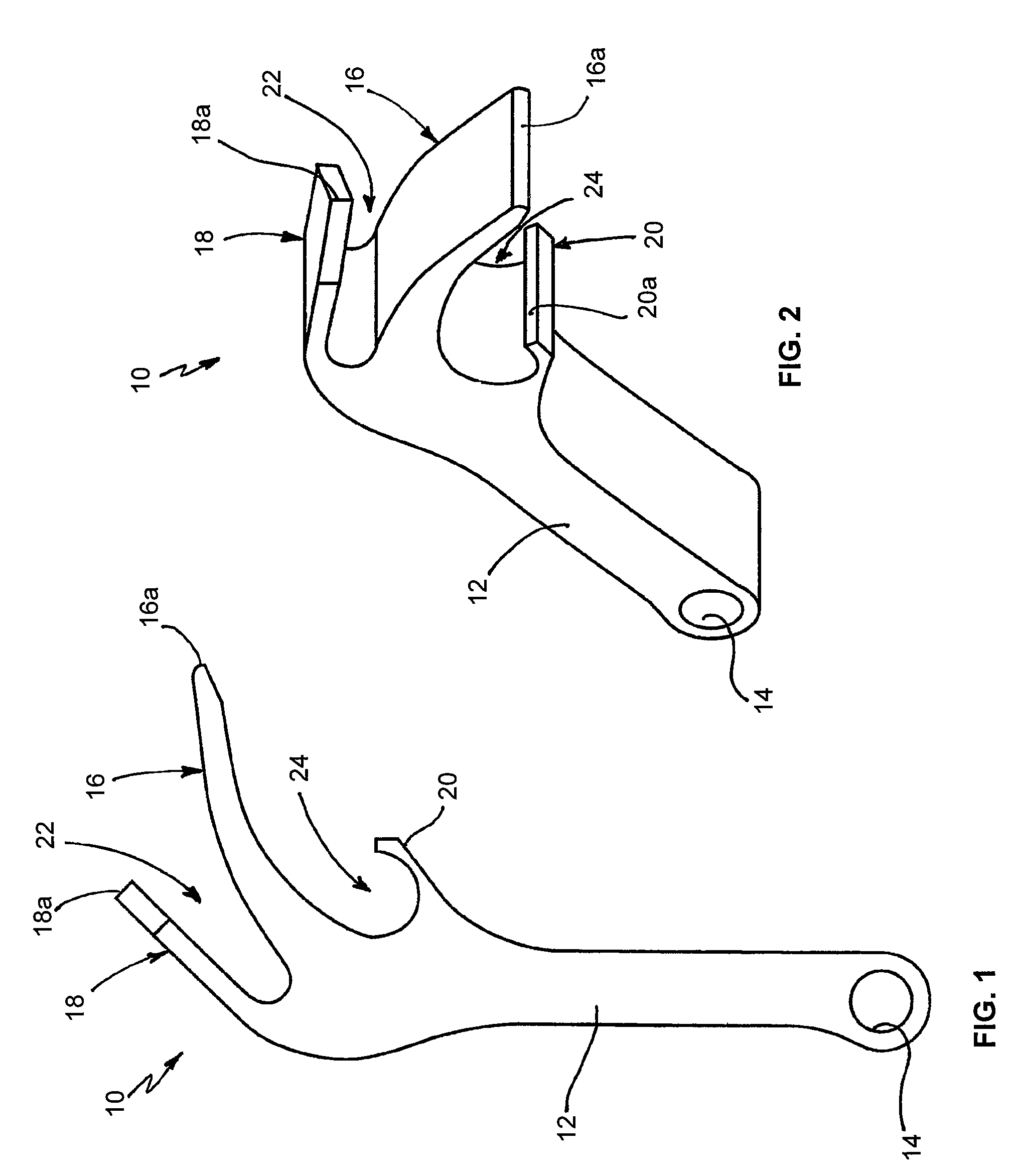
[0025]FIGS. 1 and 2 are respectively side elevation and perspective views of a pop-top can opener 10 in accordance with the principles of the present invention.

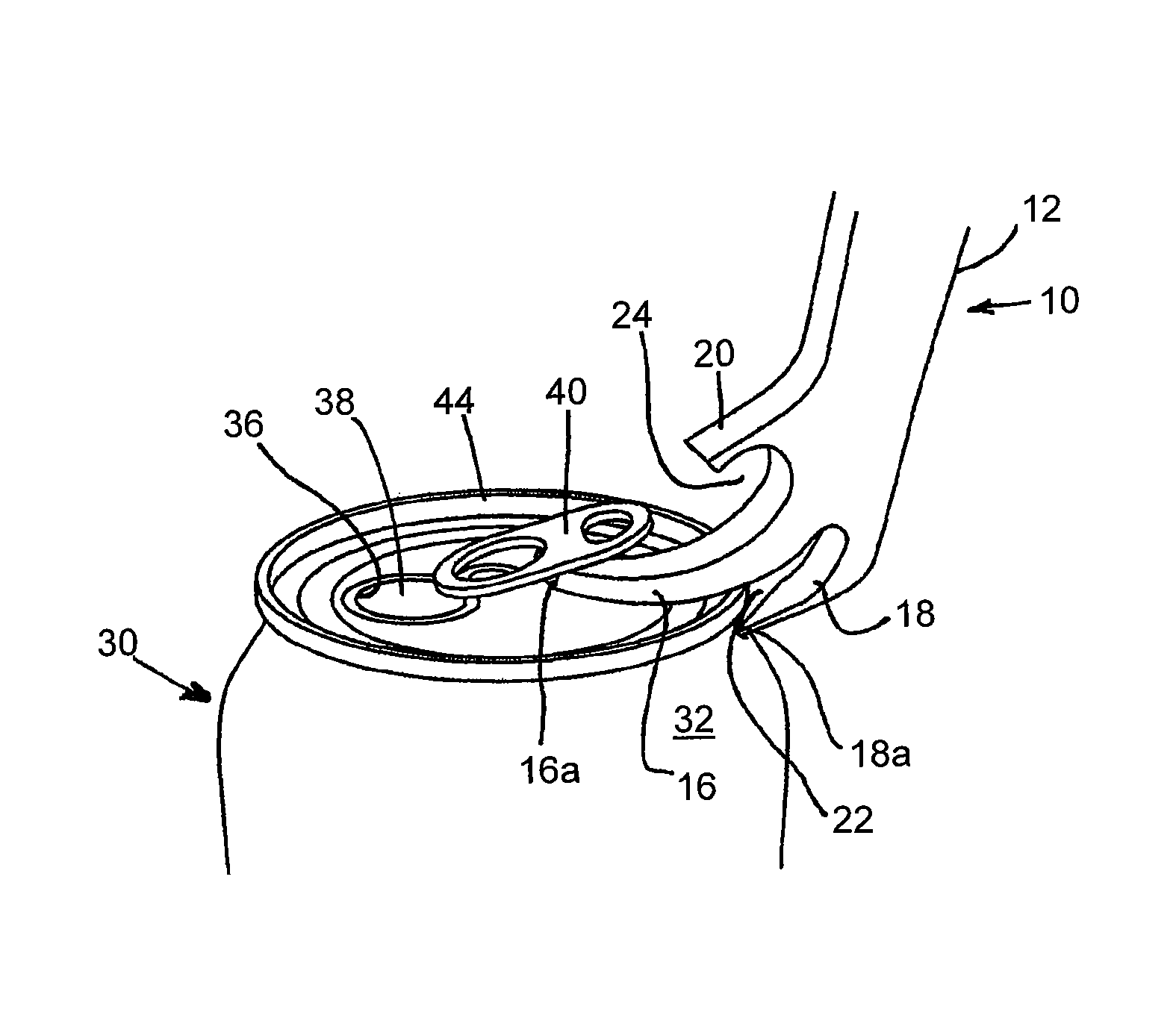
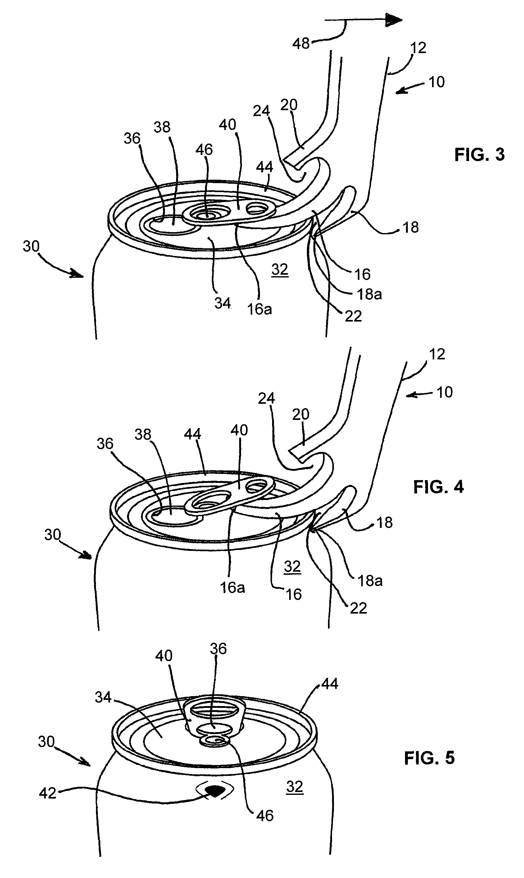
[0026]Can opener 10 includes an elongated handle 12 having one end with an aperture 14 therein. Aperture 14 is adapted to receive a support member such as a key ring or a line (not shown for simplicity) for supporting the can opener and maintaining it in a convenient location or position for use. Disposed on and extending from a second opposed end portion of handle 12 is a first arm 16. First arm 16 is generally curvilinear in shape and includes a flat distal end 16a. Also disposed on the second end of handle 12 is a second arm 18 which is generally linear and includes a pointed distal end 18a. A first space, or gap, 22 is disposed between the first and second arms 16, 18. Also disposed on and extending from the enlarged second end of handle 12 is a third arm 20 having a flat distal end 20a. A second space, or gap, 24 is disp...


PUM


Abstract

A can opener is adapted for engaging and lifting a tab attached to the flat upper surface (top) of a sealed can, with the upraised tab engaging and downwardly displacing a sealing member for opening the can. The opener includes a handle with first and second arms extending therefrom. The curvilinear first arm is adapted for positioning between the can's upper surface and the tab and for raising the tab when the handle is pivotally moved outwardly from the can's upper edge which acts as a fulcrum in engaging a lower portion of the curvilinear first arm. A second arm extending from the handle and disposed in closely spaced relation from the first arm includes a pointed end portion adapted to engage and puncture an upper lateral portion of the can to prevent formation of an air lock in the can for facilitating the discharge of the liquid contents of the can.

Description

FIELD OF THE INVENTION[0001]The present invention relates generally to can openers, and is particularly directed to an opener for a pop-top beverage can which opens a can in a manner which allows for more quickly emptying the can of its liquid contents.BACKGROUND OF THE INVENTION[0002]Early pop-top, or tab-type, cans contained a ring member attached to a sealing member disposed over an opening in the top of a can containing a liquid. The can was opened by removing the combination of the ring member and sealing member. Primarily for environmental reasons, this combination was replaced with a generally elongated tab which is manually engaged and pivotally displaced about a rivet attaching the tab to the top of the can. The pivoting tab engages a sealing member and pivotally urges the sealing member into the can in opening the can. The tab and sealing member remain attached to the top of the can. The flat top of the can is provided with a weakened score line having a generally oval sha...

Claims


Application Information

Patent Timeline
Patent Type & Authority Patents(United States)
IPC IPC(8): B67B7/44B67B7/50B67B7/40
CPCB67B7/24B67B7/403B67B7/16
Inventor ROZMUS, MICHAEL J.KIELBASA, BRUCE D.
Owner ROZMUS MICHAEL J
Why Eureka
Try Eureka