Image heating apparatus and image heating rotational body to be mounted on the image heating apparatus

a heating apparatus and rotating body technology, applied in the direction of electrographic process apparatus, instruments, optics, etc., can solve the problems of image failure, image failure, image cracks on the surface of the fusing roller, etc., and achieve excellent image quality

Inactive Publication Date: 2014-04-15
CANON KK
View PDF4 Cites 4 Cited by
  • Summary
  • Abstract
  • Description
  • Claims
  • Application Information

AI Technical Summary

Benefits of technology

[0018]The present invention is directed to an image heating apparatus having excellent image quality after the image is heated.
[0019]The present invention also provides an image heating apparatus capable of preventing scratches from being generated on the surface of a rotational body.
[0020]The present invention also provides an image heating apparatus having a capability of repairing scratches even if the scratches are generated on the surface of a rotational body.

Problems solved by technology

However, in the contact-type externally heating fusing unit, the heating member is arranged in contact with the surface of the fusing roller, so that scratches may be generated on the surface of the fusing roller.
During fusing toner images on a recording member, the surface configuration of the fusing roller is transferred onto the toner images on the recording member, image failure, such as a vertical streak, due to the scratch generated on the surface of the fusing roller may emerge on the fixed toner images.
Such a scratch may also cause the image failure.
The paper burr is liable to be generated when the knife blade becomes blunt due to abrasion in the cutting process from large-sized paper.
If the surface state of the fusing roller differs, the surface state of the toner images is differentiated along with this, resulting in glossiness unevenness.
On the other hand, in the case of low glossiness, the surface state of images is reversely uneven, so that the fluorescent light is diffusely reflected and the shape of the fluorescent lamp is not transferred.
In such a manner, the unevenness on the image surface relates to the glossiness.
Since there are various sizes of the recording member, many scratches due to the passage of paper edges exist on the surface of the fusing roller along the generating line direction.
However, granted that it is finely, the blemishing the surface reduces the surface nature, so that the reduced glossiness becomes a problem.
Furthermore, when using a sliding member for overlapping invisible fine scratches or for finely skiving the surface layer, dust and foreign materials may be pinched, so that a secondary problem of vertical streaks generated in the circumferential direction has arisen.

Method used


Image

  • Image heating apparatus and image heating rotational body to be mounted on the image heating apparatus
  • Image heating apparatus and image heating rotational body to be mounted on the image heating apparatus
  • Image heating apparatus and image heating rotational body to be mounted on the image heating apparatus

Examples


first embodiment

[0058]A first embodiment of the present invention will be described below. First, an image forming apparatus having an image heating apparatus according to the embodiment mounted thereon as a fusing unit will be described and then, an image heating apparatus according to embodiments will be described in detail.

[Configuration of Image Forming Apparatus Body]

[0059]A common method for forming unfixed toner images on a recording member as a member to be heated will be described with reference to a schematic drawing of FIG. 23.

[0060]An image forming apparatus 50 according to the embodiment is a full-color printer in that an image is formed by sequentially transferring four-color toner images of yellow, magenta, cyan, and black on one recording member P conveyed on a recording member conveying belt 9. Around a photosensitive drum 1, a charger 2, an exposure unit 3 for irradiating the photosensitive drum 1 with a laser beam corresponding to image information, and a developing unit 5 for de...

second embodiment

[0092]A second embodiment of the present invention will be described below. Like reference numerals and symbols designate like components common to the first embodiment and the description is omitted.

[0093]According to the embodiment, at least one of the heating member 112 and the fusing roller 110 reciprocates in a direction intersecting with the rotational direction of the fusing roller 110 in a state that both the members are arranged in contact with each other.

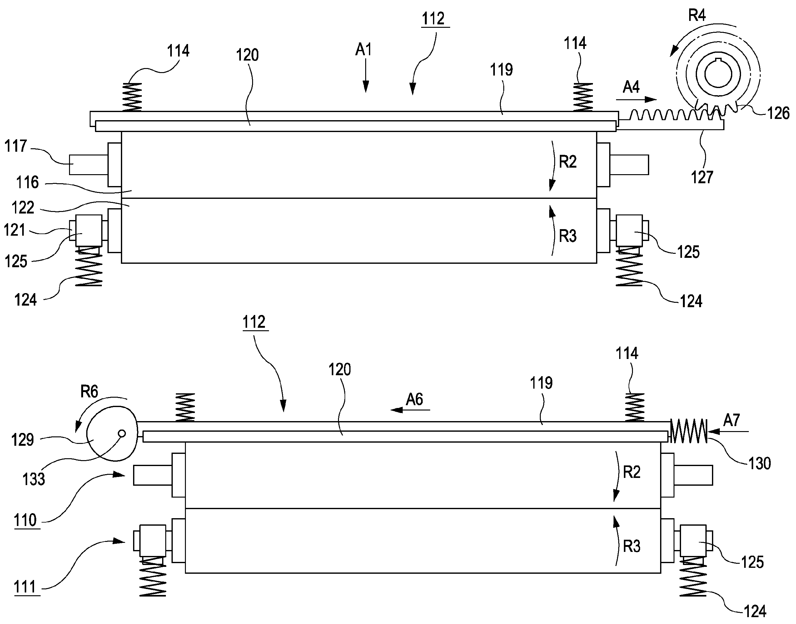
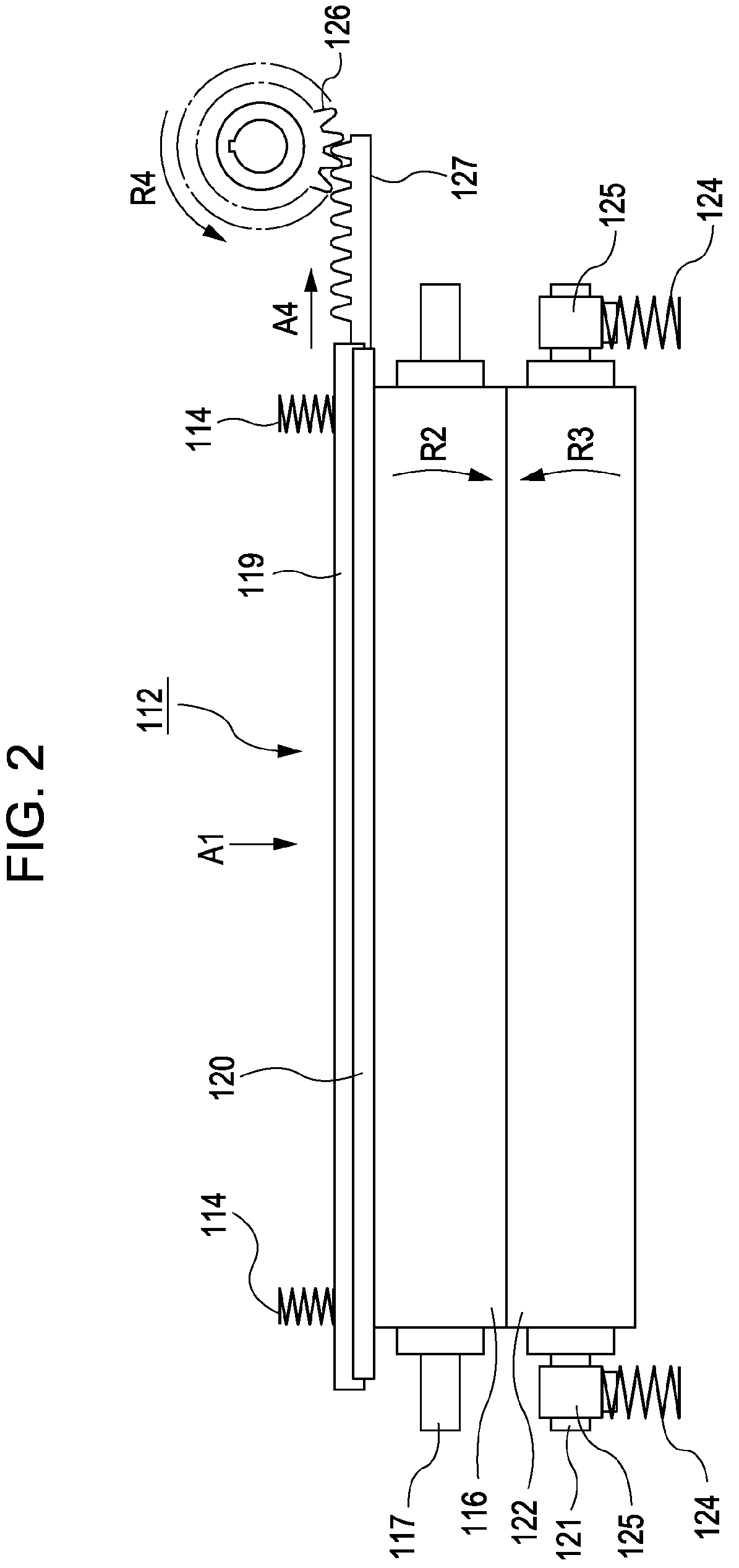
[0094]FIG. 6 is a front view of a contact-type externally heating fusing unit according to the embodiment. In the same way as in the first embodiment, the fusing roller 110 is fixed in the axial direction, and by the rotation of the fusing roller 110 in arrow R2 direction, the pressure roller 111 is rotated to follow the fusing roller 110 in arrow R3 direction.

[0095]The heating member 112 is slidable in a direction in parallel with the axis of the fusing roller 110, and is slid from one side in arrow A6 direction by a pres...

third embodiment

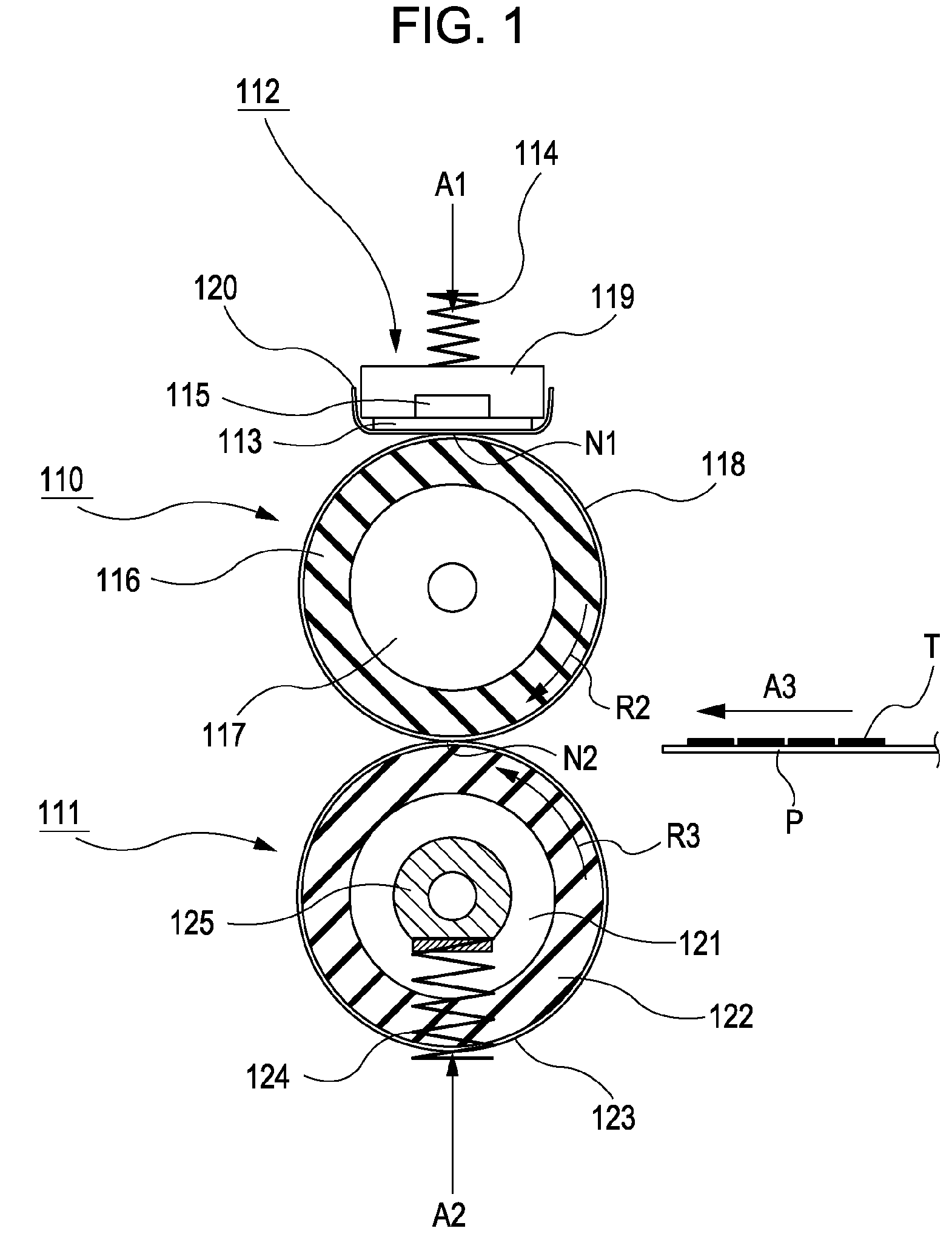
[0127]A third embodiment of the present invention will be described below. In this embodiment, the image forming apparatus is generally provided for forming unfixed toner images in the same way as in the first embodiment, so that its description is omitted. As for the contact-type externally heating fusing unit, like reference numerals and symbols designate like components common to the first embodiment and the description is omitted. According to the embodiment, at the contact heating portion N1, the surface of the fusing roller 110 is moved relative to the heating member 112 in a direction different from the rotational direction of the fusing roller 110 (the intersecting direction), so that the heating member 112 is rotated in a direction different from the rotational direction of the fusing roller 110. This will be described below in detail.

[0128]FIG. 16 is a front view of the contact-type externally heating fusing unit according to the embodiment. In the same way as in the first...


PUM


Abstract

According to embodiments, a heating member or a sliding member arranged in contact with the surface of a fusing roller is moved in an intersecting direction with the rotational direction of the fusing roller in a contact state with the heating member or the sliding member so as to prevent a scratch from being generated on the surface of the fusing roller or to repair the scratch.

Description

CROSS-REFERENCE TO RELATED APPLICATIONS[0001]This application is a continuation of U.S. patent application Ser. No. 12 / 266,433 filed Nov. 6, 2008, now U.S. Pat. No. 8,463,167 which claims the benefit of Japanese Patent Application No. 2007-292191 filed Nov. 9, 2007 and No. 2007-330948 filed Dec. 21, 2007, all of which are hereby incorporated by reference herein in their entirety.BACKGROUND OF THE INVENTION[0002]1. Field of the Invention[0003]The present invention relates to an image heating apparatus suitably used as a fusing unit mounted on an image forming apparatus, such as an electrophotographic copying machine and a laser beam printer, and an image heating rotational body mounted on the image heating apparatus.[0004]2. Description of the Related Art[0005]As a fusing unit to be mounted on an electrophotographic image forming apparatus, a system is proposed (Japanese Patent Laid-Open No. 2003-186327) in that a heating member is arranged on the surface (outer circumferential surfa...

Claims


Application Information

Patent Timeline
Patent Type & Authority Patents(United States)
IPC IPC(8): G03G21/00G03G15/20
CPCG03G15/2057G03G15/2075G03G15/2053G03G15/2025
Inventor TANAKA, MASASHIABE, ATSUYOSHIAOKI, DAISUKEKEMMOCHI, KAZUHISAMIKI, TSUTOMU
Owner CANON KK
Why Eureka
Try Eureka