
Plastic LED bulb

a technology of led bulbs and plastics, applied in the direction of electric discharge tubes/lamps, coupling device connections, lighting and heating apparatus, etc., can solve the problems of not being able to meet the needs of illumination, still taking many watts to generate adequate light, and affecting illumination effect,

Inactive Publication Date: 2014-04-22
SWITCH BULB CO INC
View PDF396 Cites 11 Cited by
  • Summary
  • Abstract
  • Description
  • Claims
  • Application Information

AI Technical Summary

Benefits of technology

This patent describes an LED bulb and a method of manufacturing it. The LED bulb has a thermally conductive plastic material inside a bulb-shaped shell and contains at least one LED. The plastic material is injected into the shell and cures at a temperature below which might damage the LEDs. The LED bulb also has a base that is designed to fit into an electrical socket. The method of manufacturing involves creating a plastic bulb-shaped shell, installing the LED in the plastic material, and curing it. Overall, the patent introduces an LED bulb with improved cooling capabilities and a method of manufacturing it that ensures the LED is not damaged during the process.

Problems solved by technology

However, LEDs have a number of drawbacks that have prevented them, so far, from being widely adopted as incandescent replacements.
Among the chief of these is that, although LEDs require substantially less power for a given light output than do incandescent bulbs, it still takes many watts to generate adequate light for illumination.
Whereas the tungsten filament in an incandescent bulb operates at a temperature of approximately 3000° (degrees) K, an LED, being a semiconductor, cannot be allowed to get hotter than approximately 120° C. The LED thus has a substantial heat problem: If operated in vacuum like an incandescent, or even in air, it would rapidly get too hot and fail.
This has limited available LED bulbs to very low power (i.e., less than approximately 3W), producing insufficient illumination for incandescent replacements.
This solution is undesirable, and in fact has not been tried, because of the common perception that customers will not use a bulb that is shaped radically differently from the traditionally shaped incandescent bulb; and also from the consideration that the heat sink may make it impossible for the bulb to fit in to pre-existing fixtures.

Method used


Image

  • Plastic LED bulb
  • Plastic LED bulb
  • Plastic LED bulb

Examples


Embodiment Construction

[0020]Reference will now be made in detail to the present preferred embodiments of the invention, examples of which are illustrated in the accompanying drawings. Wherever possible, the same reference numbers are used in the drawings and the description to refer to the same or like parts.

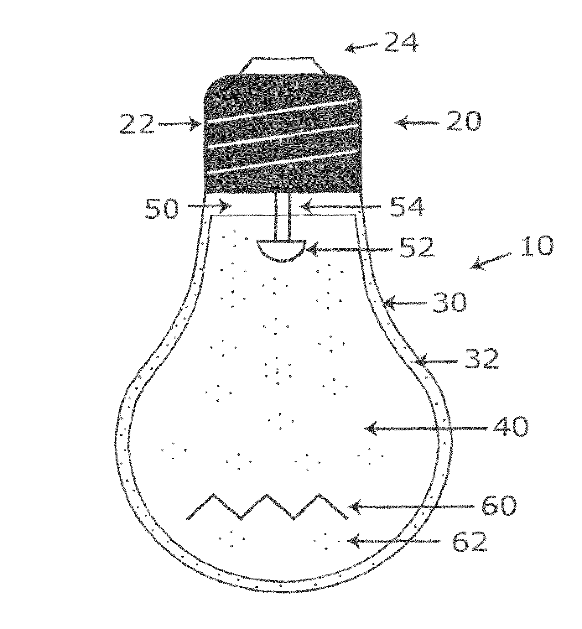
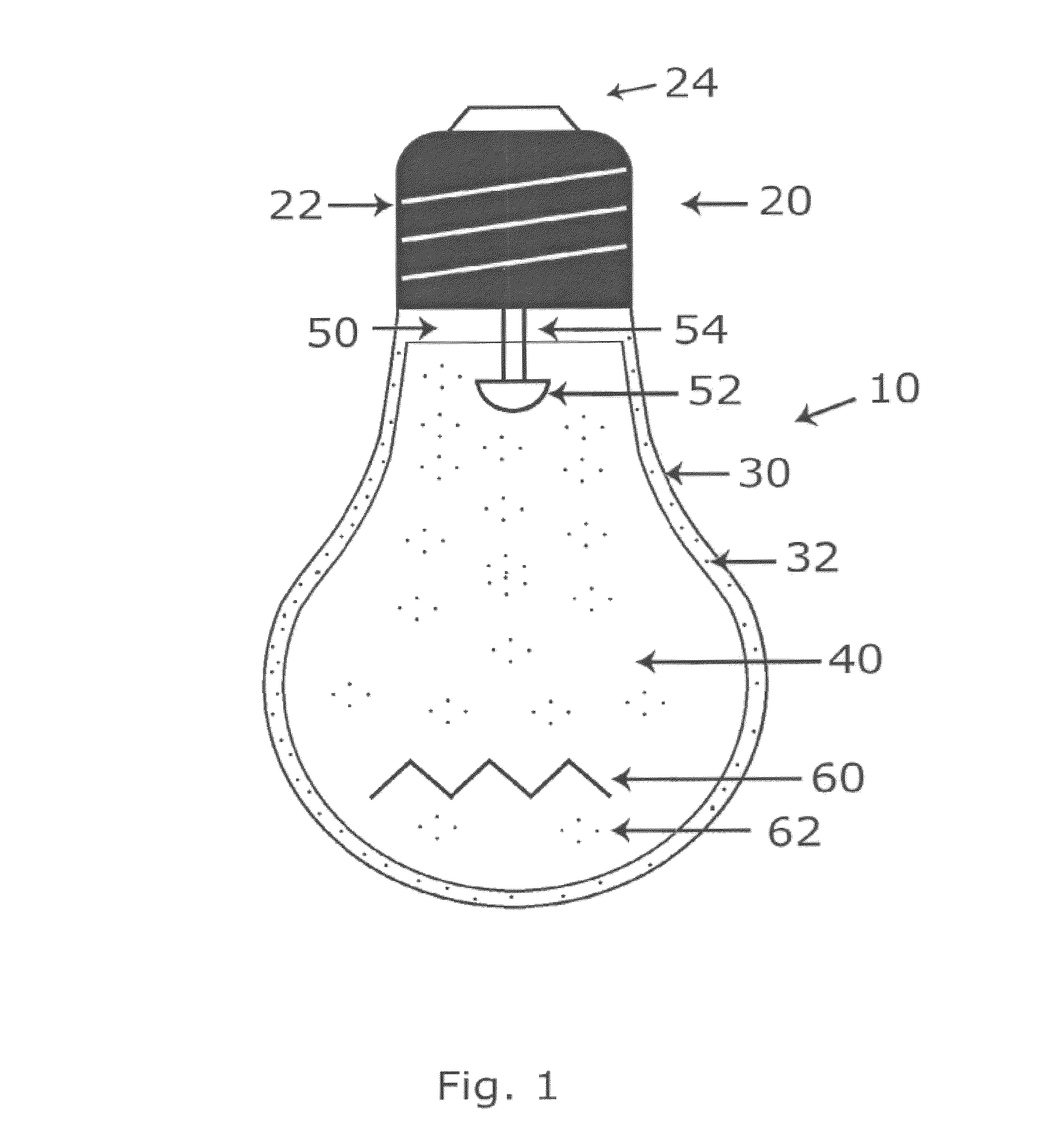
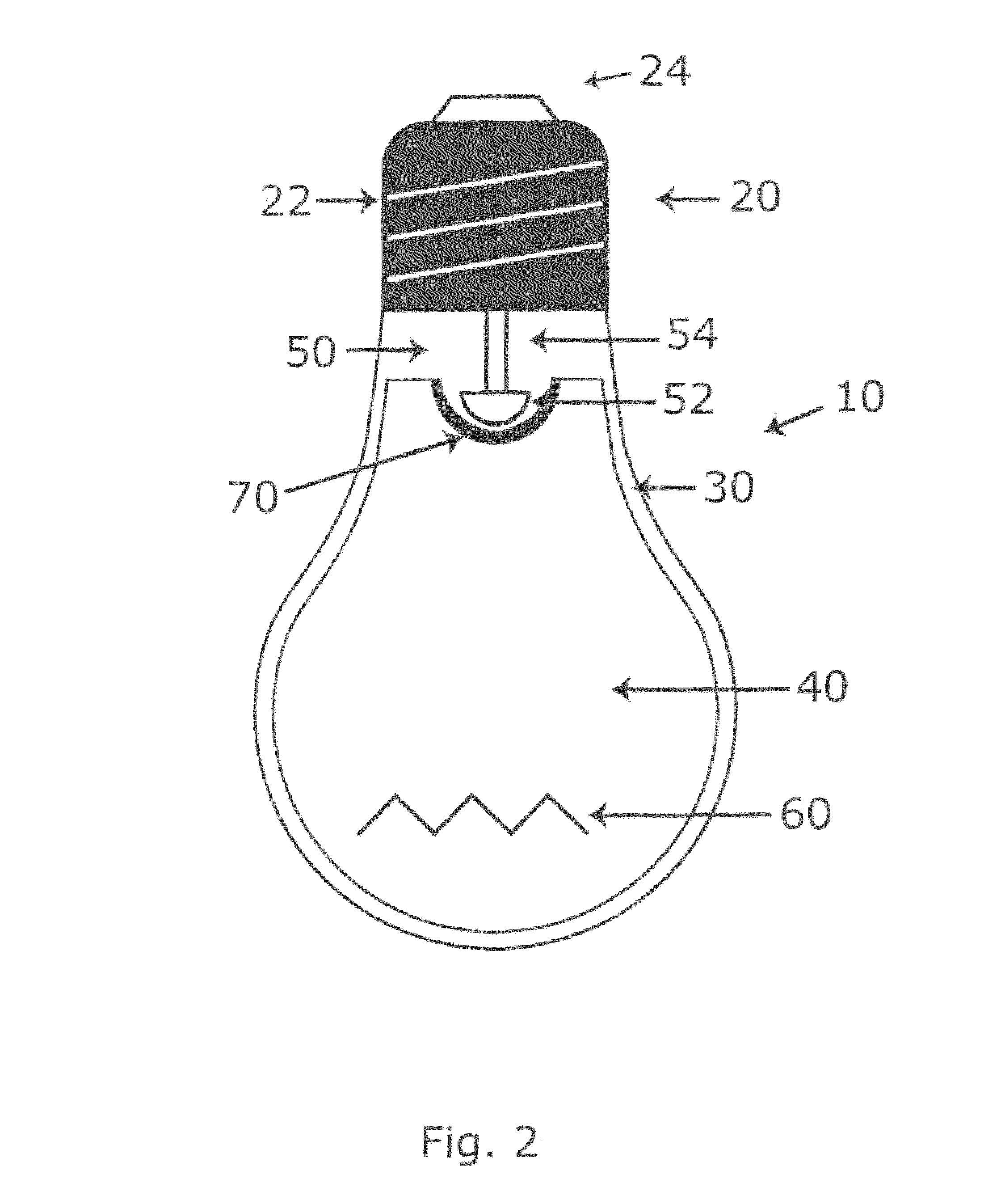
[0021]FIG. 1 is a cross-sectional view of an LED replacement bulb 10 showing the light-emitting portion of the LED mounted in a plastic material according to one embodiment. As shown in FIG. 1, the LED replacement bulb 10 includes a screw-in base 20, a plastic shell 30, an inner portion 40 containing a transparent or translucent thermally conductive material, which may be any suitable plastic material 60, and at least one LED 50. It can be appreciated that the shell 30 (or enclosure) may be any shape, or any of the other conventional or decorative shapes used for bulbs, including but not limited to spherical, cylindrical, and “flame” shaped shells 30. Alternatively, the shell 30 can be a tubular elem...


PUM

PropertyMeasurementUnit
temperatureaaaaaaaaaa
poweraaaaaaaaaa
thermally conductiveaaaaaaaaaa

Abstract

An LED bulb having a bulb-shaped shell, a thermally conductive plastic material within the bulb-shaped shell, and at least one LED within the bulb-shaped shell. The bulb also includes a base, wherein the base is dimensioned to be received within a standard electrical socket.

Description

CROSS-REFERENCE TO RELATED APPLICATION[0001]This application is filed under 35 U.S.C. §371 and claims priority to International Application Serial No. PCT / US2007 / 010469, filed Apr. 27, 2007, which claims priority to U.S. Patent Provisional Application No. 60 / 797,146 filed May 2, 2006 which is incorporated herein by this reference in its entirety.FIELD OF THE INVENTION[0002]The present invention relates to replacement of bulbs used for lighting by light emitting diode (LED) bulbs, and more particularly, to the efficient removal of the heat generated by the LEDs in order to permit the replacement bulb to match the light output of the bulb being replaced.BACKGROUND OF THE INVENTION[0003]An LED consists of a semiconductor junction, which emits light due to a current flowing through the junction. At first sight, it would seem that LEDs should be able to make an excellent replacement for the traditional tungsten filament incandescent bulb. At equal power, they give far more light output t...

Claims


Application Information

Patent Timeline
Patent Type & Authority Patents(United States)
IPC IPC(8): H01J9/395F21V9/12H01R33/22F21V9/16F21V3/04F21V5/00F21K99/00
CPCF21V5/00F21V9/12F21V3/0445F21Y2101/02F21V29/248H01J9/395H01R33/22F21K9/90F21V3/0463F21K9/135F21V9/16F21V3/00F21V29/24F21Y2111/001F21K9/50Y10T29/49117F21V29/58F21V29/85F21K9/232F21K9/60F21Y2115/10F21Y2107/00F21V3/0625F21V3/08
Inventor LENK, RONALD J.LENK, CAROLCHANDLER, DANIEL
Owner SWITCH BULB CO INC
Learn More