Image forming apparatus with resin frame and method for molding the resin frame

a technology of image forming apparatus and resin frame, which is applied in the direction of electrographic process apparatus, instruments, optics, etc., can solve the problems of imposing a limit on the reduction in size and weight, affecting the quality and insufficient profitability of conventional metal frames, so as to achieve the effect of improving color image quality and suppressing the position accuracy of color image forming units

Active Publication Date: 2014-04-22
SHARP KK
View PDF14 Cites 12 Cited by
  • Summary
  • Abstract
  • Description
  • Claims
  • Application Information

AI Technical Summary

Benefits of technology

[0013]Thus, it is a problem underlying the present invention to provide an image forming apparatus including a resin frame composed of a resin and an image forming unit that is removably inserted in the resin frame and a method for molding a resin frame, the image forming apparatus and the resin frame molding method being capable of simplifying the structure of a mold while securing the strength of the resin frame, and also suppressing decreases in the position accuracy and in the ease of operation of the image forming unit.
[0016]According to the image forming apparatus and the resin frame molding method of the present invention, since the downstream end portions, in the mold opening direction, of the side plate portion, which is provided at the peripheral edge of the base so as to extend in the direction perpendicular to the supporting surface, are integrally connected to each other and extend essentially parallel to the perimeter of the base, the strength of the resin frame can be secured. In addition, since the mold opening direction of the mold for molding the guide portion is set to the direction parallel to the orthogonal direction that is orthogonal to the insertion direction and the guide portion is molded in the direction parallel to the orthogonal direction, the distance over which the mold slides with respect to the guide portion can be reduced, and thus the structure of the mold can be simplified. Furthermore, since the mold opening direction of the mold for molding the guide portion is set to the direction parallel to the orthogonal direction and the draft of the mold is unrelated to the direction parallel to the insertion direction in which the image forming unit is inserted, a decrease in the position accuracy of the image forming unit in the orthogonal direction can be suppressed, the image forming unit can be inserted smoothly, and thus a decrease in the ease of operation of the image forming unit can be suppressed.
[0020]According to the above-described matters specifying the invention, the resin frame is formed into an H shape, which provides excellent rigidity while realizing an improvement in the section efficiency, and this makes it possible to improve the overall strength of the resin frame with a simple structure and, furthermore, to provide the base, which supports the image forming unit, in a position between the upper end portion and the lower end portion of the resin frame in the vertical direction at which the strength is increased.
[0024]According to the above-described matter specifying the invention, a decrease in the position accuracy of the color image forming unit can be suppressed, and the color image quality can be improved accordingly.

Problems solved by technology

With the recent trend toward lower costs for image forming apparatuses, conventional metal frames are not sufficiently profitable.
Moreover, with the trend toward smaller and lighter apparatuses, simplification of the structure, reduction in the number of components, and the like have been pursued, but the metal frame structures impose a limit on the reduction in size and weight.
However, in this case, there is a problem with regard to the strength.
In the case where a resin frame is molded using a mold, in order to mold a guide portion that is formed so as to extend in the insertion direction of an image forming unit, when a mold opening direction of a mold for molding the guide portion is set to a direction parallel to the insertion direction of the image forming unit, problems as described below may arise.
That is to say, in the case of forming the guide portion so as to extend in the insertion direction of the image forming unit, the distance over which the mold slides with respect to the guide portion increases, leaving problems in producing the mold in terms of the structure of the mold, the cost of the mold, and the like.
Moreover, in the case of setting the mold opening direction of the mold to the direction parallel to the insertion direction of the image forming unit, there may be problems with the position accuracy or the ease of operation of the image forming unit because of the draft of the mold.

Method used


Image

  • Image forming apparatus with resin frame and method for molding the resin frame
  • Image forming apparatus with resin frame and method for molding the resin frame
  • Image forming apparatus with resin frame and method for molding the resin frame

Examples


Embodiment Construction

[0035]Hereinafter, an embodiment according to the present invention will be described with reference to the drawings. It should be noted that the embodiment described below is an example embodying the present invention and should not be construed as limiting the technical scope of the present invention.

[0036]Description of Overall Configuration of Image Forming Apparatus

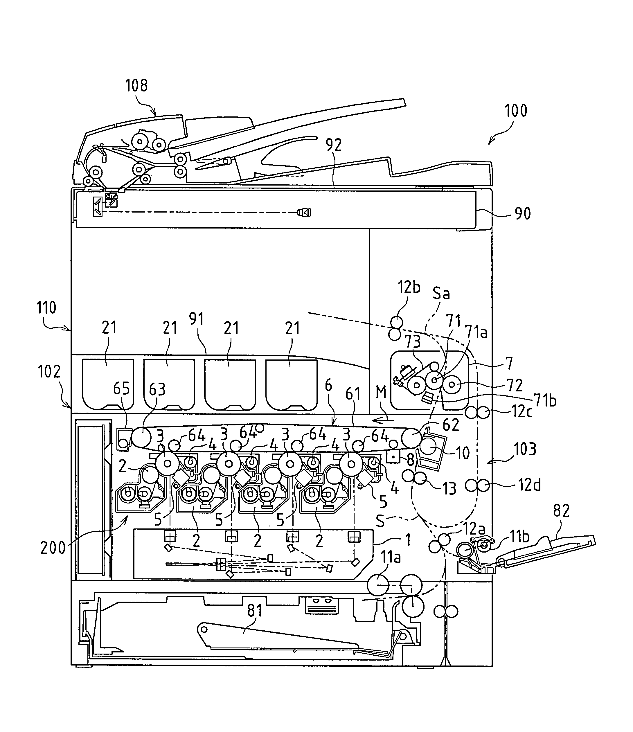
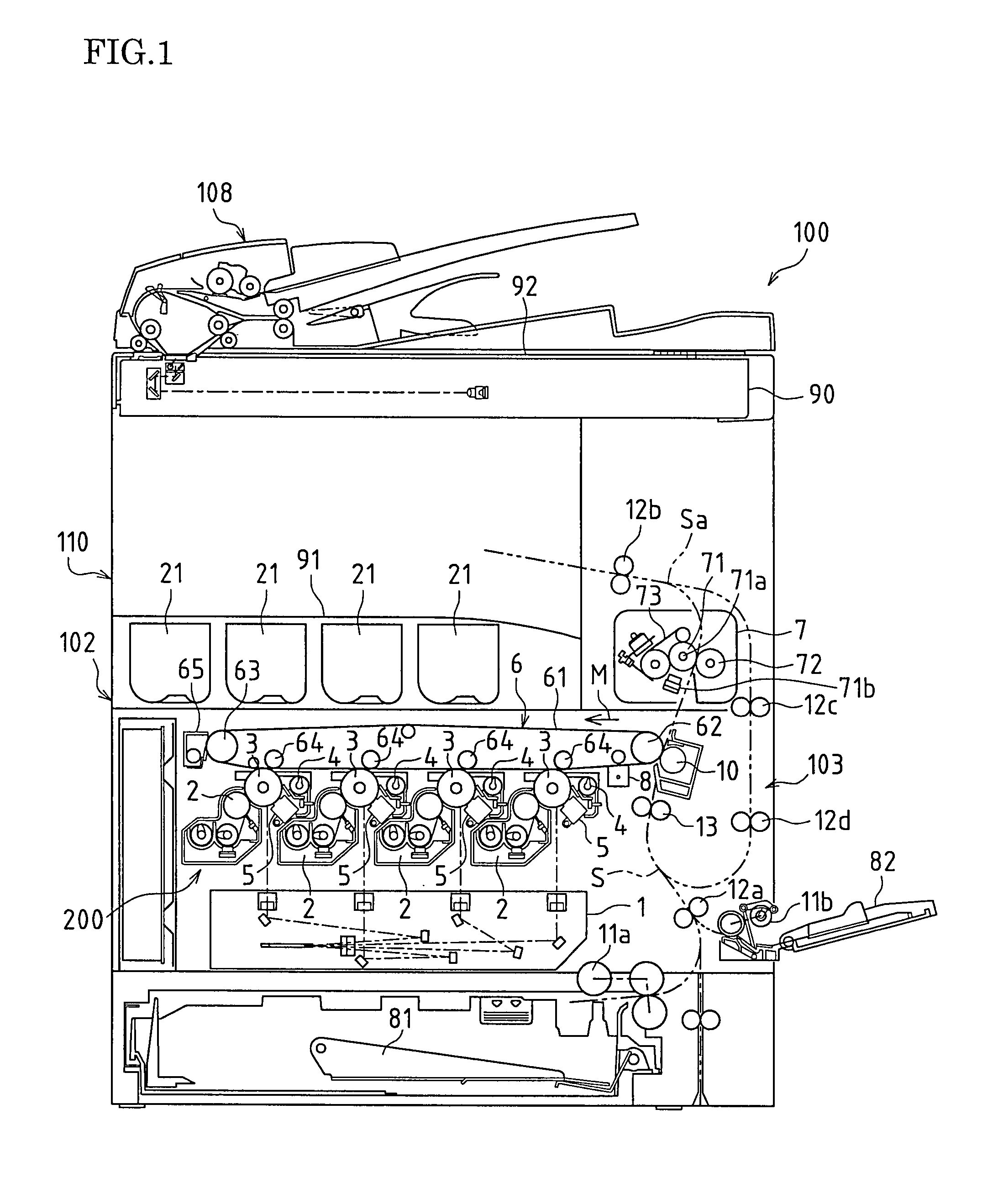
[0037]FIG. 1 is a schematic cross-sectional view of an image forming apparatus 100 according to the present embodiment as seen from the front.

[0038]The image forming apparatus100 shown in FIG. 1 is a color image forming apparatus that forms images in multiple colors or in a single color on sheets of recording paper or the like (hereinafter referred to as “recording paper”) in accordance with image data transmitted from outside. The image forming apparatus 100 includes an original reading apparatus 108 and an apparatus main body 110, and the apparatus main body 110 is provided with an image forming portion 102 and a p...


PUM

PropertyMeasurementUnit
draft angleaaaaaaaaaa
thicknessaaaaaaaaaa
diameteraaaaaaaaaa

Abstract

An image forming apparatus of the present invention includes a resin frame composed of a resin and an image forming unit that is removably inserted in the resin frame. The resin frame includes a base having a supporting surface that supports the image forming unit, a guide portion that extends in the base in an insertion direction in which the image forming unit is inserted along the supporting surface and that guides the image forming unit in the insertion direction while limiting movement of the image forming unit in an orthogonal direction that is orthogonal to the insertion direction, and a side plate portion that is provided at a peripheral edge of the base so as to extend in a direction perpendicular to the supporting surface, the base, the guide portion, and the side plate portion being integrally molded from a resin. A mold opening direction of a mold for molding the guide portion is set to a direction parallel to the orthogonal direction, and downstream end portions of the side plate portion in the mold opening direction are integrally connected to each other and extend essentially parallel to the perimeter of the base.

Description

CROSS-REFERENCE TO RELATED APPLICATIONS[0001]This application claims priority under 35 U.S.C. §119(a) on Patent Application No. 2010-109516 filed in Japan on May 11, 2010, the entire contents of which are herein incorporated by reference.BACKGROUND OF THE INVENTION[0002]Conventionally, frames serving as the frameworks of image forming apparatuses such as copiers, printers, facsimile machines, or digital multifunctional machines have been metal frame structures assembled by fastening or welding metal pressed components or metal-based steel products together.[0003]With the recent trend toward lower costs for image forming apparatuses, conventional metal frames are not sufficiently profitable. Moreover, with the trend toward smaller and lighter apparatuses, simplification of the structure, reduction in the number of components, and the like have been pursued, but the metal frame structures impose a limit on the reduction in size and weight.[0004]In view of the reduction in cost, size, ...

Claims


Application Information

Patent Timeline
Patent Type & Authority Patents(United States)
IPC IPC(8): G03G15/00G03G15/01G03G21/16
CPCG03G2221/1603G03G21/1619G03G2221/1678G03G15/0142
Inventor YAMAUCHI, KOHICHITAKEDA, SHINICHITOMITA, NORIONAKAZAWA, SHINJITAGUCHI, NORIAKIISOMI, KENICHIMOCHIZUKI, SHUICHI
Owner SHARP KK
Why Eureka
Try Eureka