Vibrating dental plate and accessories
a dental plate and accessory technology, applied in the field of vibration dental plates, can solve the problems of reducing the speed of tooth movement, reducing the degree of orthodontic treatment, so as to achieve maximum flexibility, speed up boney remodeling, and enhance boney remodeling
- Summary
- Abstract
- Description
- Claims
- Application Information
AI Technical Summary
Benefits of technology
Problems solved by technology
Method used
Image
Examples
example 1
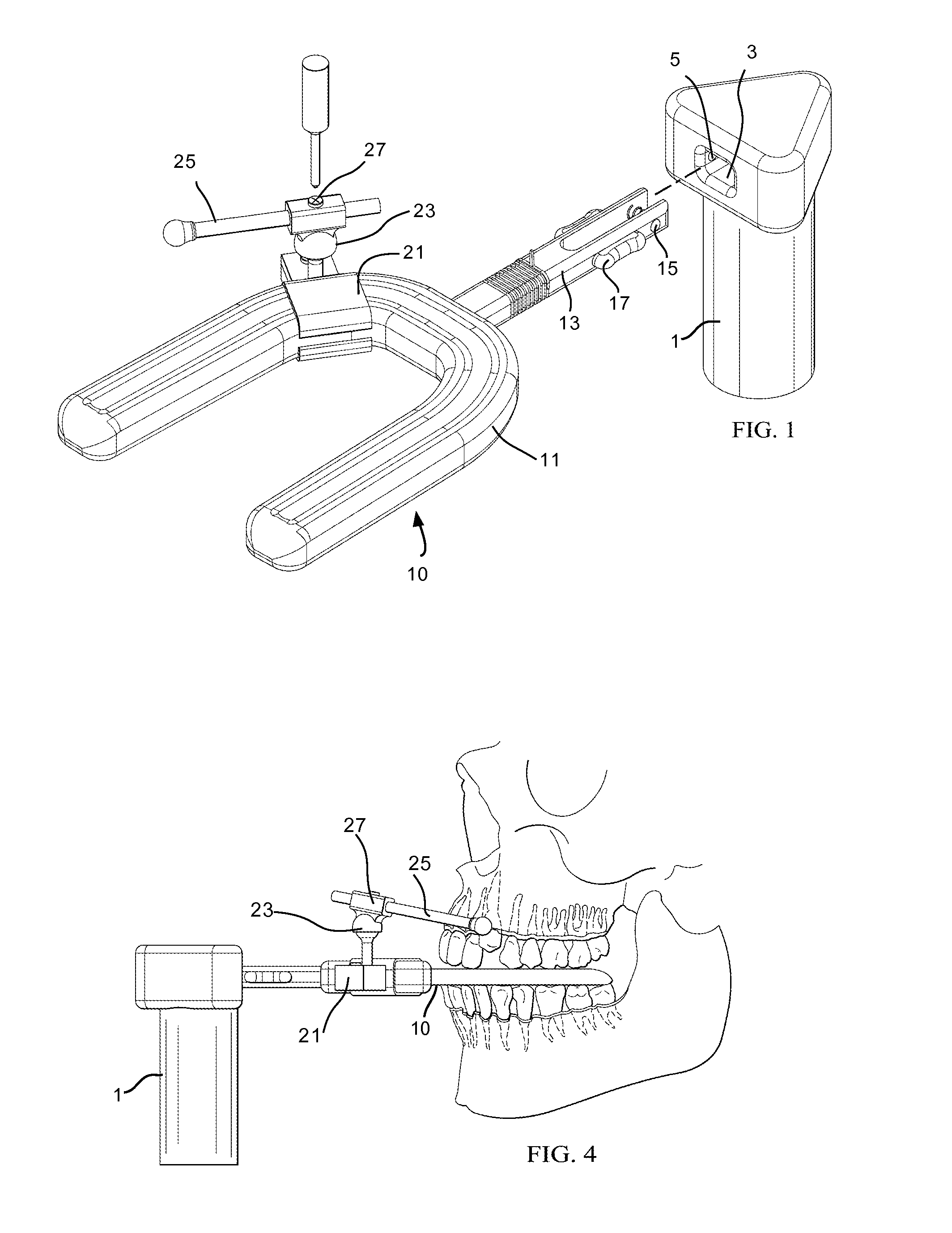
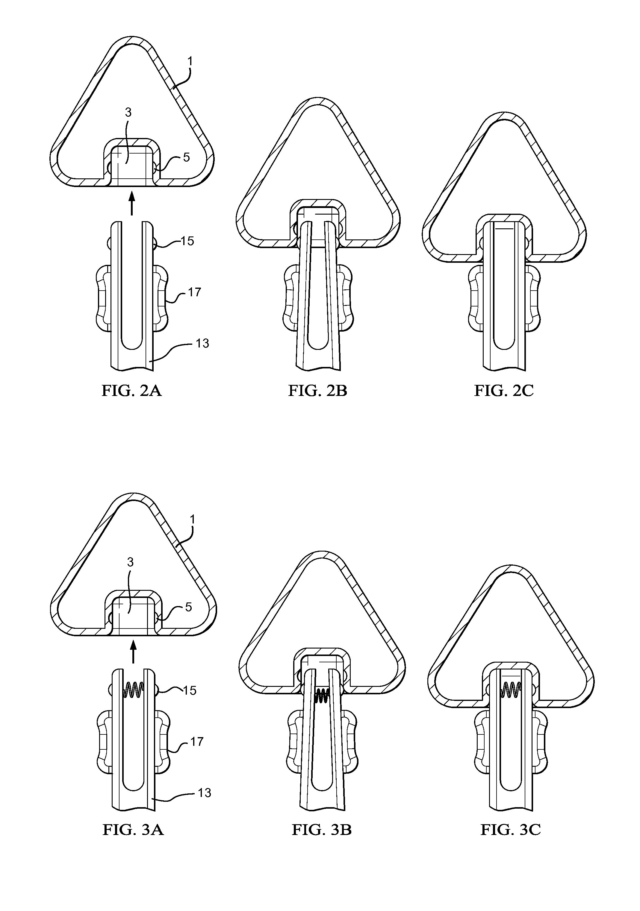
[0063]The device of FIGS. 1-3 illustrates a snap fit between the prong 13 of the dental plate 10 and the socket 3 of the vibrator 1. In the embodiments shown, the prong has protrusions 15 that fit into recessions 5 inside the socket 3. Button 17 can be used to release the protrusion from the recessions when the dental plate is removed. Various means of biasing the protrusions outward so as to lock into the socket are available, including coil, leaf or torsion springs, and the like. Alternatively, if the prong is bifurcated or is otherwise compressible the material itself may provide the biasing means. We have illustrated a rectangular prong and socket, but other shapes are possible requiring only that the socket accommodate the prong in a snap or locking fit. Further, we have illustrated the prong having the protrusions and release button, but the reverse is also possible and the protrusions can be contained in the socket of the vibrator.
example 2
[0064]FIGS. 1 and 4 illustrate the wand system designed to reach severely misaligned teeth. In this embodiment, wand 25 is made of a flexible material, such as metal, and can be completely or partially coated with a polymeric material such as silicone. The wand 25 is removably attached to the dental plate 10 on either the bite plate 11 or the prong 13 via clamp 21 and optionally a connector 23 that functions to reversibly and optionally rotationally couple the clamp and the wand. In use, the wand is flexed to meet the recessed or misaligned teeth and the clamp 21 can be positioned as needed on the bite plate or the prong. In one embodiment, a tightening or locking means 27 is used to tighten, fix or lock the connector into position so that the wand sits in a particular orientation. In preferred embodiments, the clamp is attached to the prong, thus remaining outside the mouth during use.
example 3
[0065]The device of FIGS. 5A and 5B show a much simpler means of reaching recessed teeth, comprising adding risers 31 to the bite plate 11 at appropriate locations. The risers 31 can be glued, heat welded, welded or otherwise bonded to the bite plate, or can be attached by an attaching means, such as a screw 35, rivet, bolt, nail, staple, pins, and the like. Shown is a separate screw 35 that passes through the riser and threadably connects to the bite plate. Risers that are bonded to the bite plate are preferred since this provides the maximum flexibility in placement of the riser. We have illustrated risers for individual teeth, but risers can also be elongated to contact multiple teeth, as needed for a particular dentition.
PUM
 Abstract
Description
Claims
Application Information
 - R&D
- Intellectual Property
- Life Sciences
- Materials
- Tech Scout
- Unparalleled Data Quality
- Higher Quality Content
- 60% Fewer Hallucinations
Browse by: Latest US Patents, China's latest patents, Technical Efficacy Thesaurus, Application Domain, Technology Topic, Popular Technical Reports.
© 2025 PatSnap. All rights reserved.Legal|Privacy policy|Modern Slavery Act Transparency Statement|Sitemap|About US| Contact US: help@patsnap.com


