
Cooled Stator Thermal Barrier

A technology of thermal barrier layer and stator, which is applied in the direction of stator, engine manufacturing, machine/engine, etc., can solve the problems of impossible leading edge area, too large, etc., and achieve the effect of saving coolant

Active Publication Date: 2018-09-11
ANSALDO ENERGIA IP UK LTD
View PDF9 Cites 0 Cited by
  • Summary
  • Abstract
  • Description
  • Claims
  • Application Information

AI Technical Summary

Problems solved by technology

Therefore, this cooling scheme requires an excessive coolant to hot gas pressure ratio and is impractical for the leading edge region of the thermal barrier

Method used


Image

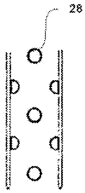
  • Cooled Stator Thermal Barrier
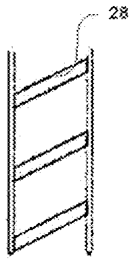
  • Cooled Stator Thermal Barrier
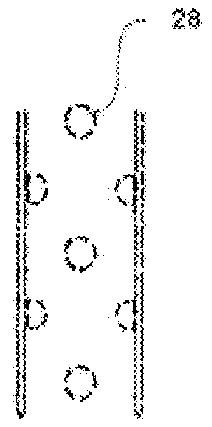
  • Cooled Stator Thermal Barrier

Examples


Embodiment Construction

[0052] according to figure 1 , a gas turbine 1 of which only small details are shown here, has a stator 2 and a rotor 3 , each of which is also only partially shown. Sections of the vanes 4 of the stator 2 and of the vane carrier 5 are discernible. The vane 4 is attached to a vane carrier 5 . The stator thermal barrier layer 10 is mounted on the vane carrier 5 . Only one turbine blade 6 of the rotor 3 can be discerned here, which blade is arranged between the two guide vanes 4 . The axis of rotation 9 , around which the rotor 3 rotates during operation of the gas turbine 1 and which defines the axial direction of the gas turbine 1 , is indicated here in dashed lines. Axial in this context therefore means parallel to the axis of rotation 9 , whereas the radial direction is perpendicular to the axis of rotation 9 and the circumferential direction is oriented around the axis of rotation 9 along a circular passage. Thus, the rotor blade 6 is arranged axially between the two gu...


PUM


Abstract

The present invention provides a stator thermal barrier for a gas turbine having a rotor defining an axis of rotation, the stator thermal barrier comprising a plurality of cooling units arranged in an array along the axis of rotation, each of the cooling units comprising a surface an outer portion of a hot gas path to the gas turbine, and an inner plate positioned on the outer portion and exposed to cooling air, wherein the inner plate includes a plurality of inlet openings formed through the inner plate to introduce cooling air into the outer portion , and thus impinges on the hot gas-washed wall cooling the outer portion comprising a cooling air channel formed therein having a first central portion for receiving cooling air, and a second helix surrounding the first central portion A portion for conveying cooling air outward to the cooling air outlet of the second helical portion. Initial studies of the cooling scheme proposed in this invention showed an estimated cooling air saving of 40% compared to conventional designs.

Description

technical field [0001] The invention relates to a cooled stator thermal barrier for a gas turbine, and a gas turbine equipped with such a cooled stator thermal barrier. Background technique [0002] In the installed state, the stator thermal barrier is located on the stator and / or on the casing of the gas turbine. They are usually mounted on a vane carrier and form the radial boundary of the hot gas path of the gas turbine in the region of the rotor blades of the rotor of the gas turbine. Typically, a plurality of such stator thermal barriers are arranged adjacent to each other in the circumferential direction with respect to the axis of rotation of the rotor, forming a closed ring of individual stator thermal barriers. The separate stator thermal barrier here forms a ring segment. The stator thermal barrier protects the casing and / or vane carrier from exposure to the hot gases of the gas turbine. The outer side of the stator thermal barrier is exposed to the hot gas, whi...

Claims


Application Information

Patent Timeline
Patent Type & Authority Patents(China)
IPC IPC(8): F01D25/12
CPCF05D2250/15F05D2240/11F05D2260/201F05D2260/202F05D2260/22141F01D11/10F05D2240/15F01D9/04F01D25/12
Inventor P.V.拉特廷A.A.塞德洛夫A.蒂洛夫M.普洛蒂斯特伊
Owner ANSALDO ENERGIA IP UK LTD
Learn More