Device, Method, and System for Creating Dynamic Horizon Effect Lighting

a dynamic horizon and lighting technology, applied in the direction of electrical appliances, etc., can solve the problems of affecting sleep, releasing heat and light, glow of light, etc., and achieve the effects of low electricity demand, low heat emission, and extensive li

Active Publication Date: 2020-09-03
BARRETT GREGORY
View PDF0 Cites 0 Cited by
  • Summary
  • Abstract
  • Description
  • Claims
  • Application Information

AI Technical Summary

Benefits of technology

[0032]Technology in the realm of lighting control has evolved substantially since the invention of the incandescent light bulb. Current lighting options in terms of light bulbs for common usage include the traditional incandescent, halogen, fluorescent, CFL (compact fluorescent), and LED (light emitting diodes or alternatively, light emitting device) bulbs. How light is emitted with each of these different sources may vary in substantial ways, but they have a common functional thread. For each of these three types of light sources, a passage of electricity through thin filament causes excitement and heating of the filament resulting in a glow of light. The luminescence of light, its intensity or brightness, is affected by the level of electrical input. With fluorescent light bulbs, passage of electricity through a filament creates heat within the filament, leading to a secondary effect that causes excitement of fluorophore molecules which provides the main source of light. In regards to incandescent bulbs, brightness of light emission is directly proportional to the amount of electrical passage and level of excitement of filament wires. For LED light bulbs, passage of electricity through semi-conductor filament causes movement of electrons, changes in atomic bonds, which results in release of heat and light. At the most basic level, the effect of electricity on the degree of luminescence of these such light sources effectively enables adjustment of light by means of controlling electrical input. The means of controlling adjustment of light may further be digitized. More complex lighting systems require reliable light sources that can sustain longer term usage without intense electrical input that would otherwise create too much heat. LED lighting is the current preferred standard source for lighting given its low electricity demands, quality of light emission, low heat emission, extensive life, and versatile light emission control. For purposes of this invention, LED lighting is the preferred type of light source. However, any of the above described types of light bulbs or any type of light bulbs in general that can achieve the same type of performance described herein may be used.

Problems solved by technology

For each of these three types of light sources, a passage of electricity through thin filament causes excitement and heating of the filament resulting in a glow of light.
For LED light bulbs, passage of electricity through semi-conductor filament causes movement of electrons, changes in atomic bonds, which results in release of heat and light.
More complex lighting systems require reliable light sources that can sustain longer term usage without intense electrical input that would otherwise create too much heat.
This light wave is highly stimulating and long exposure to this level of stimulation after evening hours can interfere with sleep.
Excessive exposure to blue light stimulation and in particular to irregular patterns of such exposure may cause serious disruption to bodily functions at a cellular level, leading to physical and mental dysfunction at a macro level.
Prior art within the industry of indoor lighting have failed to adequately address the problem of simulating natural sunlight patterns for optimum experience absorption by the ipRGCs of human retina.
While current technology does provide for a controlled timing and exposure to certain light intensities and as well manage the fading transition of light over time, the problem remains that the luminescence of light is produced from a fairly static source and the experience of such lighting effect is relegated to very limited space which does not follow the user as would be the case in an outdoor setting.
As such, the entire range of sunlight transition is limited within the space of the fixture.
While multiple fixtures may be strategically positioned within an indoor space, the lack of coordination between the fixtures as well as their limiting boxed shape detracts from their ability to simulate the natural transition of sun light above an outdoor horizon.

Method used


Image

  • Device, Method, and System for Creating Dynamic Horizon Effect Lighting
  • Device, Method, and System for Creating Dynamic Horizon Effect Lighting

Examples


Embodiment Construction

[0056]Reference will now be made in detail to exemplary aspects of the present invention which are illustrated in the accompanying drawings. Wherever possible, the same reference numbers will be used throughout the drawings to refer to the same or like parts.

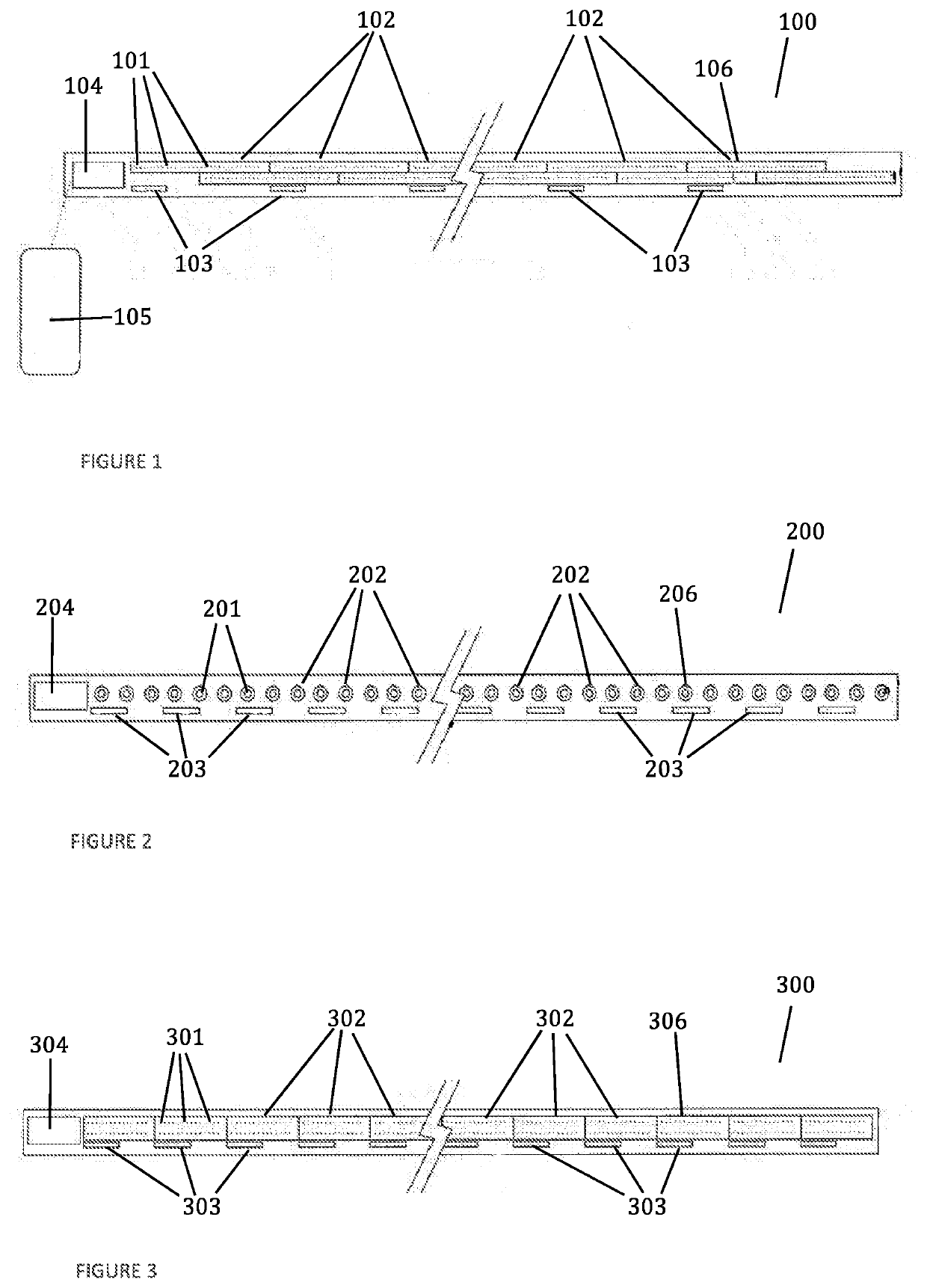
[0057]FIGS. 1-3 provides separate embodiments of the device of this invention comprising a length of the system 100, 200, 300. The given length of the system as presented in FIGS. 1-3 containing one or more lighting elements. Said one or more lighting elements 101, 201, 301 contained and organized within a modular unit (also referred herein alternatively as a modular subsection) 102, 202, 302. Each modular unit 102, 202, 302 is in direct communication with a power supply 103, 203, 304. Each modular unit 102, 202, 302 is also in direct communication with a controller 104, 204, 304. Each said controller 104, 204, 304 is in direct communication with a control program 105 which directs operation of the system according to a computer...


PUM


Abstract

An inventive solution directed to an apparatus and system for creating a dynamic ambient lighting experience wherein the level of brightness increases and decreases along a horizonal path to create an impression of linear movement. This simulates the traversal of the sun along its horizon. The device comprising subsection units which may be coordinated to increase or decrease length. The time and speed for dimming and brightening of light from start to finish along the length of the device may be defined by preconfigured parameters or customized to desired setting. The device creating a diurnal pattern of light transition and movement along the length of an indoor space subject to the peripheral view of the observer.

Description

CROSS REFERENCE TO RELATED APPLICATIONS[0001]This nonprovisional utility patent application incorporates by reference in its entirety and claims benefit to provisional patent application No. 62 / 919,148, having the filing date of Mar. 1, 2019, pursuant to 35 U.S.C. § 119(e).FEDERALLY SPONSORED RESEARCH OR DEVELOPMENT[0002]Not applicable.REFERENCE TO SEQUENCE LISTING, A TABLE, OR A COMPUTER LISTING APPENDIX[0003]Not applicable.COPYRIGHT NOTICE[0004]A portion of the disclosure of this patent document contains material that is subject to copyright protection. The copyright owner has no objection to the facsimile reproduction by anyone of the patent document or patent disclosure as it appears in the Patent and Trademark office, patent file or records, but otherwise reserves all copyright rights whatsoever.BACKGROUND OF INVENTIONField of the Invention[0005]The present inventive subject matter relates to a method, device, and system for indoor lighting that achieves a dynamic transitional ...

Claims


Application Information

Patent Timeline
Patent Type & Authority Applications(United States)
IPC IPC(8): H05B45/10H05B47/19
CPCH05B45/10H05B47/19H05B47/155
Inventor BARRETT, GREGORY
Owner BARRETT GREGORY
Why Eureka
Try Eureka