Eureka AIR delivers breakthrough ideas for toughest innovation challenges, trusted by R&D personnel around the world.

Vibrating dental plate and accessories

a dental plate and accessory technology, applied in the field of vibrating dental devices, can solve the problems of reducing the speed of tooth movement, reducing the efficiency of orthodontic treatment, so as to achieve maximum flexibility, speed up boney remodeling, and enhance boney remodeling

Active Publication Date: 2012-02-16
ADVANCED ORTHODONTICS & EDUCATION ASSOC LLC
View PDF12 Cites 47 Cited by
  • Summary
  • Abstract
  • Description
  • Claims
  • Application Information

AI Technical Summary

Benefits of technology

"The patent text describes an improvement to orthodontic tooth movement by using a unique connector between the extraoral vibration motor and the removable bite plate. This connector allows for individualized application of force to each tooth, which is necessary for speeding up the movement of the teeth. The invention also includes the use of risers, which are small button-like devices that are attached to the bite plate to reach recessed teeth. The risers can be of different shapes and can be attached using adhesive, heat weld, or other bonding means. The use of risers allows for selective removal as the dentition changes during treatment. Overall, the invention improves the speed and effectiveness of orthodontic treatment."

Problems solved by technology

The speed of the required boney remodeling can therefore become a rate-limiting characteristic for the speed of movement of any particular tooth.
Therefore, if the same magnitude of force is not applied to each individual tooth within a single dentition, the speed of tooth movement and perfection of the orthodontic treatment will be slowed as an undesirable consequence.

Method used


Image

  • Vibrating dental plate and accessories
  • Vibrating dental plate and accessories
  • Vibrating dental plate and accessories

Examples


example 1

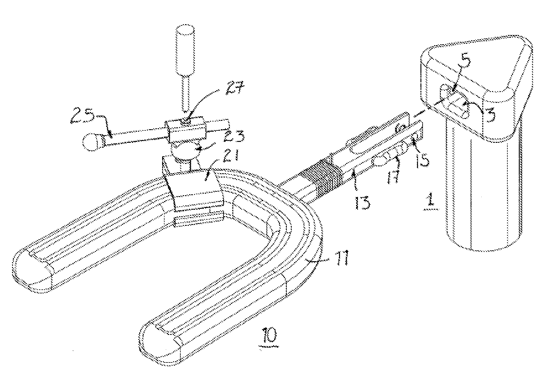
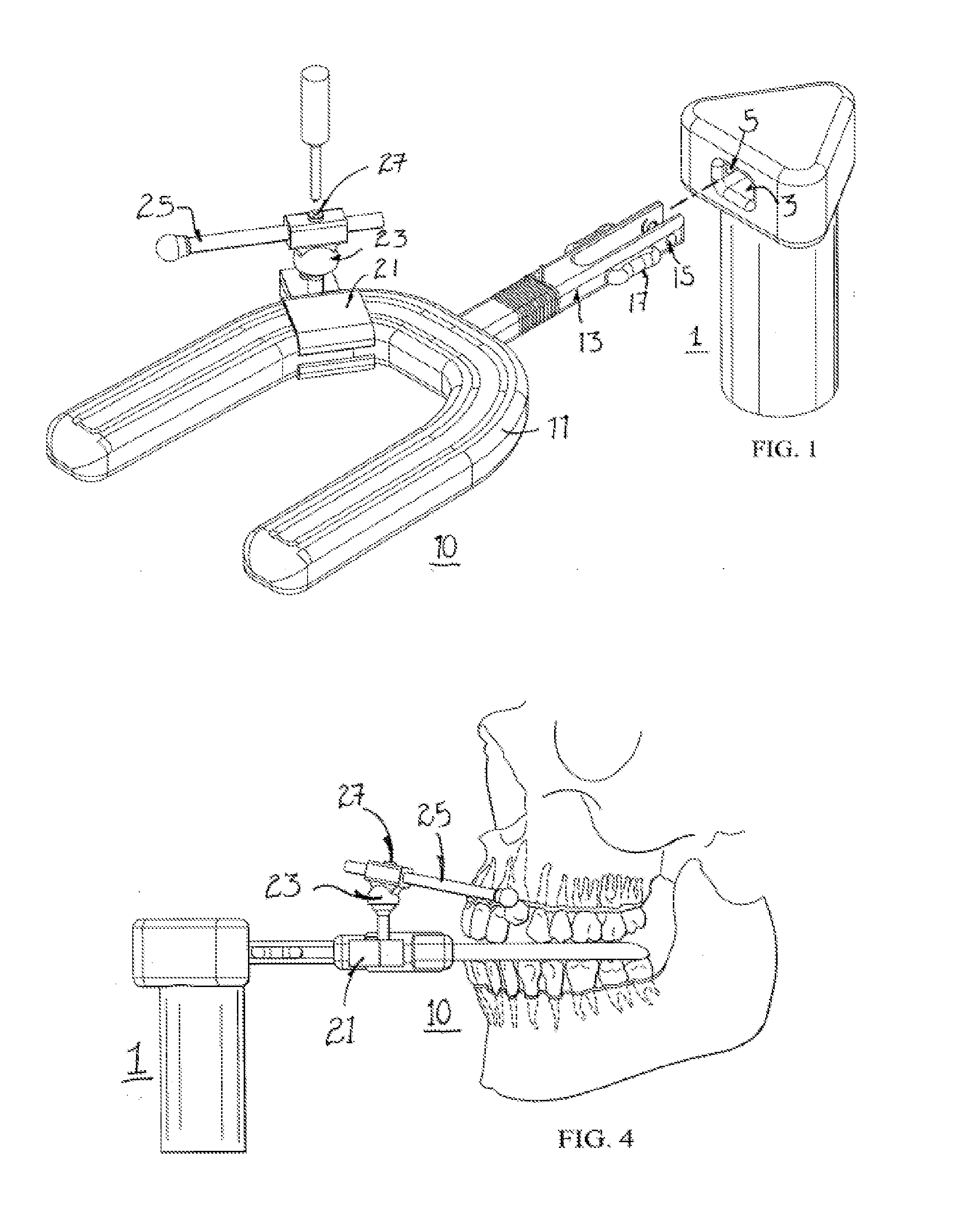
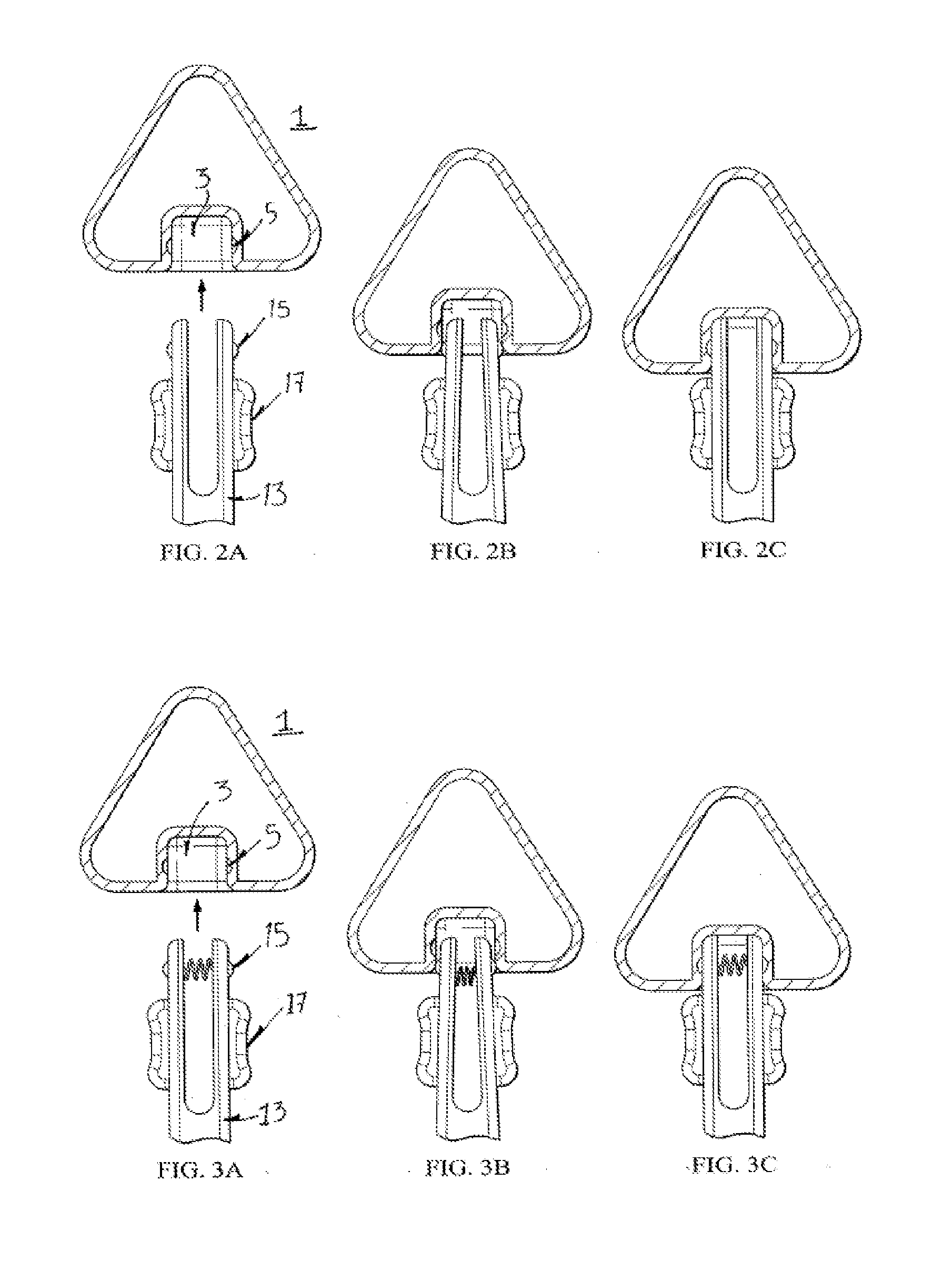
[0061]The device of FIGS. 1-3 illustrates a snap fit between the prong 13 of the dental plate 10 and the socket 3 of the vibrator 1. In the embodiments shown, the prong has protrusions 15 that fit into recessions 5 inside the socket 3. Button 17 can be used to release the protrusion from the recessions when the dental plate is removed. Various means of biasing the protrusions outward so as to lock into the socket are available, including coil, leaf or torsion springs, and the like. Alternatively, if the prong is bifurcated or is otherwise compressible the material itself may provide the biasing means. We have illustrated a rectangular prong and socket, but other shapes are possible requiring only that the socket accommodate the prong in a snap or locking fit. Further, we have illustrated the prong having the protrusions and release button, but the reverse is also possible and the protrusions can be contained in the socket of the vibrator.

example 2

[0062]FIGS. 1 and 4 illustrate the wand system designed to reach severely misaligned teeth. In this embodiment, wand 25 is made of a flexible material, such as metal, and can be completely or partially coated with a polymeric material such as silicone. The wand 25 is removably attached to the dental plate 10 on either the bite plate 11 or the prong 13 via clamp 21 and optionally a connector 23 that functions to reversibly and optionally rotationally couple the clamp and the wand. In use, the wand is flexed to meet the recessed or misaligned teeth and the clamp 21 can be positioned as needed on the bite plate or the prong. In one embodiment, a tightening or locking means 27 is used to tighten, fix or lock the connector into position so that the wand sits in a particular orientation. In preferred embodiments, the clamp is attached to the prong, thus remaining outside the mouth during use.

example 3

[0063]The device of FIGS. 5A and 5B show a much simpler means of reaching recessed teeth, comprising adding risers 31 to the bite plate 11 at appropriate locations. The risers 31 can be glued, heat welded, welded or otherwise bonded to the bite plate, or can be attached by an attaching means 35, such as a screw, rivet, bolt, nail, staple, pins, and the like. Shown is a separate screw 35 that passes through the riser and threadably connects to the bite plate. Risers that are bonded to the bite plate are preferred since this provides the maximum flexibility in placement of the riser. We have illustrated risers for individual teeth, but risers can also be elongated to contact multiple teeth, as needed for a particular dentition.


PUM


Abstract

Vibrating dental devices and accessories are provided, including a unique snap fit dental plate and vibrator connection; risers for adjusting the thickness of a dental plate; a pointer or wand that can be clamped onto a dental plate to reach even severely misaligned teeth; a cushioned dental plate having a non-Newtonian fluid therein that allows conformation of the cushion to the dentition, but hardens on use to allow the transmission of vibration to the teeth. Accessories such as carrying cases and docking stations are also provided.

Description

PRIOR RELATED APPLICATIONS[0001]This application claims priority to U.S. Ser. No. 61 / 151249, filed Feb. 10, 2009 and incorporated by reference herein.FEDERALLY SPONSORED RESEARCH STATEMENT[0002]Not applicable.REFERENCE TO MICROFICHE APPENDIX[0003]Not applicable.FIELD OF THE INVENTION[0004]The invention relates to vibrating dental devices for correcting malocclusion, and various accessories relating to same.BACKGROUND OF THE INVENTION[0005]Orthodontics is a dental specialty that treats malocclusion through the movement of teeth as well as control and modification of facial growth. This process is usually accomplished by using a continuous mechanical force to induce bone remodeling, thereby enabling the teeth to move to a better position. In this approach, orthodontic appliances provide a continuous static force to the teeth via an archwire connected to brackets affixed to each tooth or via a removable appliance such as an aligner, or some similar accessory, that fits over the dentiti...

Claims


Application Information

Patent Timeline
Patent Type & Authority Applications(United States)
IPC IPC(8): A61C7/06A61C19/02A61C7/08
CPCA61C1/07A61C7/06A61C7/008A61C7/00
Inventor LEVENS, LAWRENCETARVER, W. BRENT
Owner ADVANCED ORTHODONTICS & EDUCATION ASSOC LLC
Why Eureka
Eureka Blog
Learn More