Image stabilization apparatus and image pickup apparatus

a technology of image stabilization and image plane, which is applied in the field of image stabilization apparatus and image pickup apparatus, can solve the problems of large calculation amount for obtaining the blur amount in the image plane, inability to ignore the influence of parallel movement, and large shooting magnification, so as to reduce the calculation amount and minimize the error amount. , the effect of accurate image stabilization

Inactive Publication Date: 2014-04-29
CANON KK
View PDF22 Cites 6 Cited by
  • Summary
  • Abstract
  • Description
  • Claims
  • Application Information

AI Technical Summary

Benefits of technology

[0016]The present invention is made in view of the aforementioned problems, and has an object to provide an image stabilization apparatus and an image pickup apparatus which enable accurate image stabilization without a control failure, reduces a calculation amount, and can minimize an error amount accompanying a change in principal point position of a shooting optical system, in whatever state an angular movement and a parallel movement coexist.

Problems solved by technology

However, when close-up shooting is performed for shooting a flower or the like, the shooting magnification is very large, and the influence of parallel movement cannot be ignored.
H07-225405 has the problem that the calculation amount for obtaining the blur amount in the image plane becomes tremendous, and the algorithm of calculation becomes very complicated.
Further, the fact that the rotation center position n is ∞ means that the movement due to the angle in the pitching direction or in the yawing direction is absent, and this movement cannot be detected by the angular velocity sensor.
The correction amount can be calculated by using the output of the two acceleration sensors, but the precision is low and the calculation amount becomes tremendous.
Further, by the mathematical expression in this case, the correction calculation of the movement in the optical axis direction cannot be made.

Method used


Image

  • Image stabilization apparatus and image pickup apparatus
  • Image stabilization apparatus and image pickup apparatus
  • Image stabilization apparatus and image pickup apparatus

Examples


embodiment 1

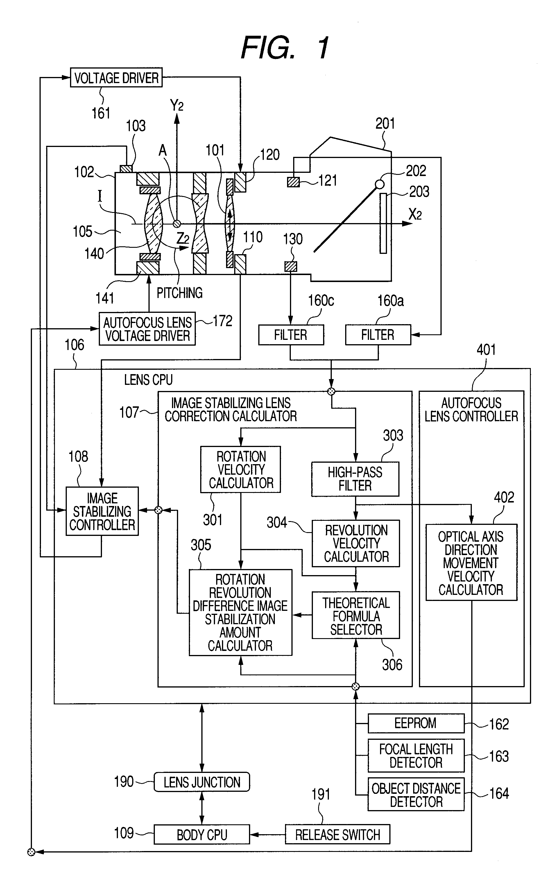
[0048]In the following embodiment, the shake movement of the camera held by human hands, and an image movement which occurs on an image plane as a result of the shake movement of the camera will be expressed by “rotation revolution movement expression” with the movement model expressed by a rotation movement and a revolution movement and a geometrical-optical expression being combined.

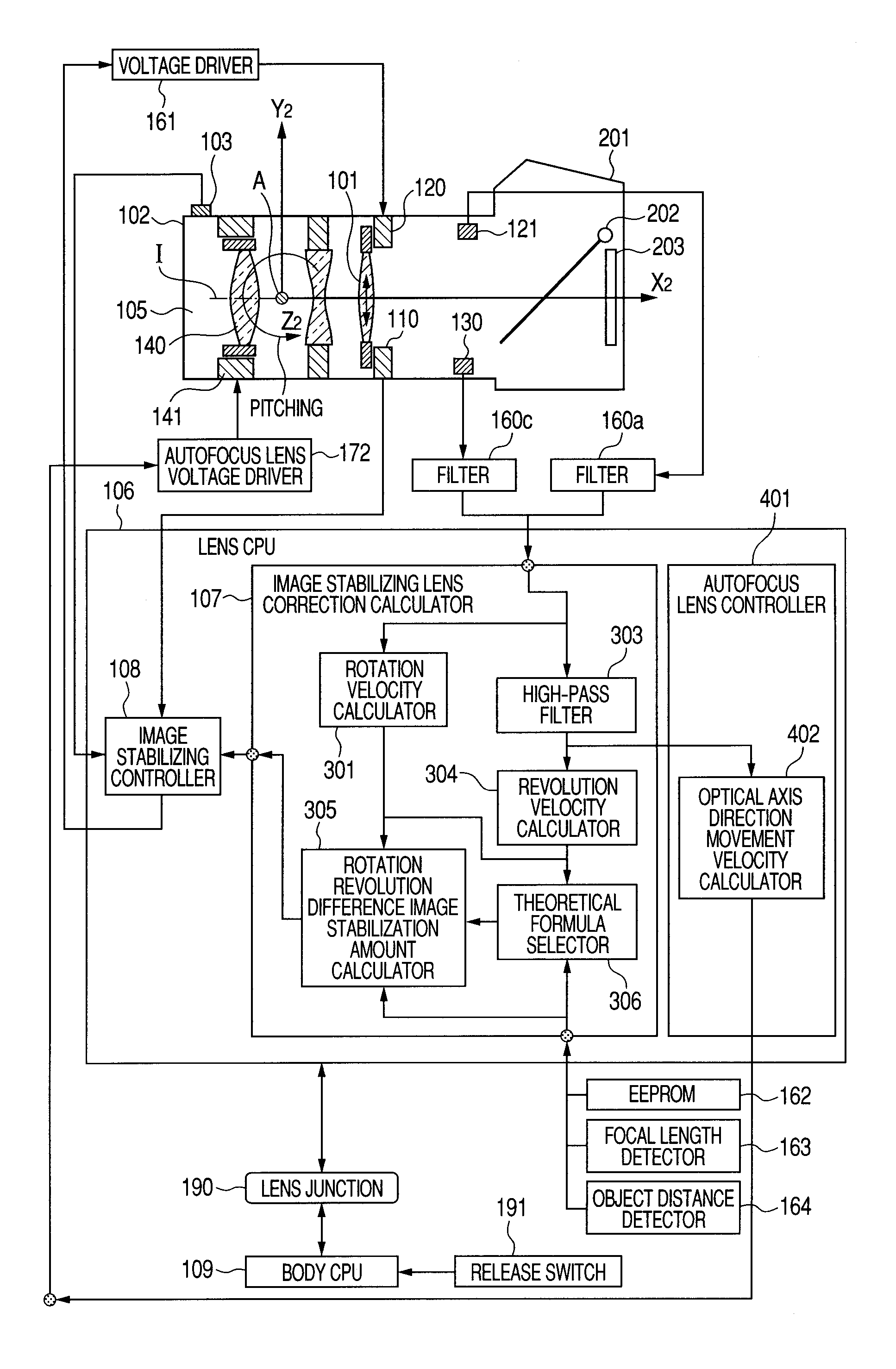
[0049]The present embodiment is an image stabilization apparatus which calculates a camera movement from the measured values of an accelerometer and an angular velocity sensor, and the rotation revolution movement expression, and further calculates an image movement. By performing drive control of a part or whole of the shooting lens or a part or whole of the image pickup device based on a calculated value of the image movement, the image blur is corrected. Alternatively, the present invention provides an image stabilization apparatus which corrects an image blur by performing image processing of a sho...

embodiment 2

[0198]By using FIGS. 19A and 19B, embodiment 2 will be described. In embodiment 1, the error ratio at each shooting imaging magnification is obtained by using expression (33), and from the result of the sum of products of the value, the position of the accelerometer 121 where the error ratio becomes the minimum is obtained. However, in the present embodiment, the error ratio at each shooting imaging magnification obtained by using expression (33) is multiplied by a shooting frequency to weight.

[0199]As described in embodiment 1, to the error ratio function at each shooting imaging magnification obtained by using expression (33), the shooting frequency at each shooting imaging magnification known as a result of the earnest study of the present applicant is multiplied. The shooting frequency is illustrated in FIG. 19A, and the result of multiplying the error ratio function when the accelerometer 121 is disposed at the shooting magnification β=0.5 by the shooting frequency is illustrat...

embodiment 3

[0203]By using FIGS. 22A and 22B, embodiment 3 will be described. The same flow as in FIGS. 7A and 7B according to embodiment 1 is included. Therefore, the same reference numerals and characters are used for the same flow, and the description will be omitted.

[0204]After revolution angular velocity calculation of S1100 of FIGS. 22A and 22B, the flow proceeds to S2610. In S2610, it is determined whether the imaging magnification of shooting is 0.2 or more (predetermined value or more). In the case of 0.2 or more, the flow proceeds to S2620, and in the case of less than 0.2 (less than the predetermined value), the flow proceeds to S1130. In S1130, rotation movement correction calculation is performed as in embodiment 1.

[0205]In S2620, it is determined whether or not the revolution angular velocity with respect to the rotation angular velocity is between −0.9 and +0.9 (predetermined value). If it is within ±0.9, the flow proceeds to S1120. When it is less than −0.9 or exceeds +0.9, the ...


PUM


Abstract

An image stabilizer has a shooting optical system shooting an object whose principal point moves between first and second principal points in an optical axis direction, an acceleration detector detecting acceleration applied to the image stabilizer and disposed between the first and second principal points in the optical axis direction. An angular velocity detector detecting angular velocity applied to the image stabilizer, an acceleration detector disposed between principal points for proximity and infinity shootings and detecting acceleration applied to the image stabilizer, a rotation angular velocity calculator calculating rotation angular velocity component around the principal point of the shooting optical system based on the angular velocity detector, a revolution angular velocity calculator calculating revolution angular velocity component around the object based on the acceleration detector and the rotation angular velocity calculator, and a controller performing image stabilization control based on a difference between the rotation and revolution angular velocity components.

Description

CROSS-REFERENCE TO RELATED APPLICATIONS[0001]This application is a national stage application of International Application No. PCT / JP2010 / 057729, filed Apr. 23, 2010 whose benefit is claimed and which claims the benefit of Japanese Patent Application No. 2009-140255, filed Jun. 11, 2009, whose benefit is also claimed.TECHNICAL FIELD[0002]The present invention relates to an image stabilization apparatus which prevents deterioration of a shot image by correcting an image blur due to shake, and an image pickup apparatus including the image stabilization apparatus.BACKGROUND ART[0003]FIG. 23 is a view showing an outline of an image stabilization apparatus included in the conventional camera. A shake which occurs to the camera has six degrees of freedom in total, which are rotational movements of three degrees of freedom constituted of pitching, yawing and rolling movement, and translation movements of three degrees of freedom constituted of movements in an X-axis, a Y-axis and a Z-axis ...

Claims


Application Information

Patent Timeline
Patent Type & Authority Patents(United States)
IPC IPC(8): H04N5/228H04N5/235
CPCH04N5/23258G02B27/646H04N5/23287G03B5/00G03B2217/005H04N23/6812H04N23/687
Inventor NOTO, GOROMASUDA, SHINICHI
Owner CANON KK
Why Eureka
Try Eureka