
Antenna tuning on an impedance trajectory

an impedance trajectory and antenna technology, applied in the direction of antennas, electricly long antennas, electrical equipment, etc., can solve the problems of increasing communications challenges, increasing the space available for radiating structures, and unable to provide high-quality communications with these devices

Inactive Publication Date: 2014-04-29
GOOGLE TECHNOLOGY HOLDINGS LLC
View PDF22 Cites 260 Cited by
  • Summary
  • Abstract
  • Description
  • Claims
  • Application Information

AI Technical Summary

Benefits of technology

This solution effectively adjusts antenna impedance to maintain optimal signal levels across various operating conditions, reducing detuning and improving communication quality in devices with limited space, by dynamically interpolating tuning states based on detected signal levels and device usage.

Problems solved by technology

As the number of mode combinations, features and functions in wireless communications devices increase, providing high quality communications with these devices becomes increasingly difficult.
While these applications and electronic functions are being used, ensuring that communications signals have a clear, unobstructed path to and from the antenna presents a unique challenge.
The communications challenges further increase as a result of the wide range of transmission requirements associated with the various communications modes that the device is expected to support.
However, as handset designers continue to shrink their products for the user's convenience, the space available for radiating structures is becoming increasingly limited.
Limited space and limited sizes of radiating elements causes communications devices to be more susceptible to severe detuning caused by mismatch resulting from hand or body proximity.

Method used


Image

  • Antenna tuning on an impedance trajectory
  • Antenna tuning on an impedance trajectory
  • Antenna tuning on an impedance trajectory

Examples


Embodiment Construction

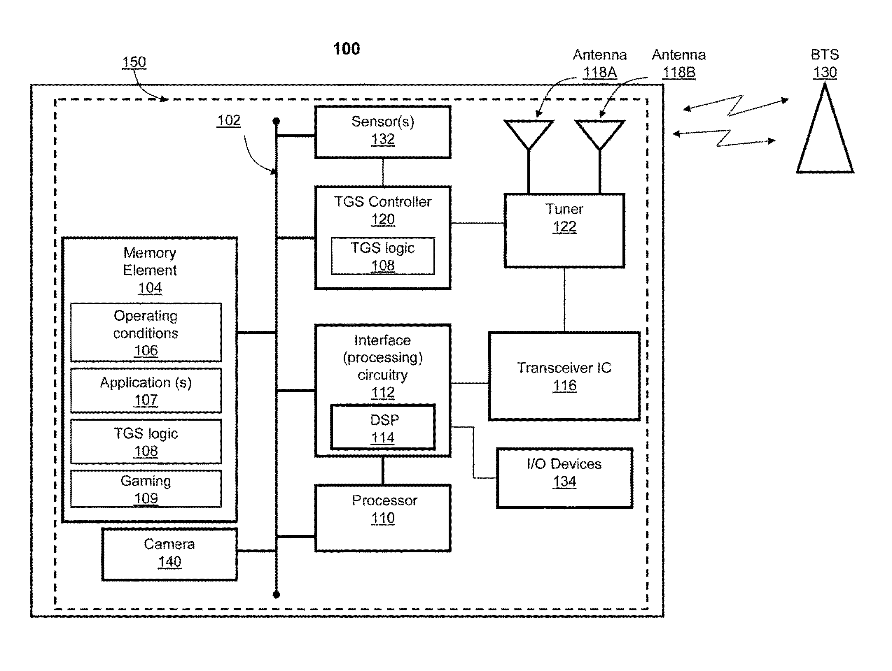
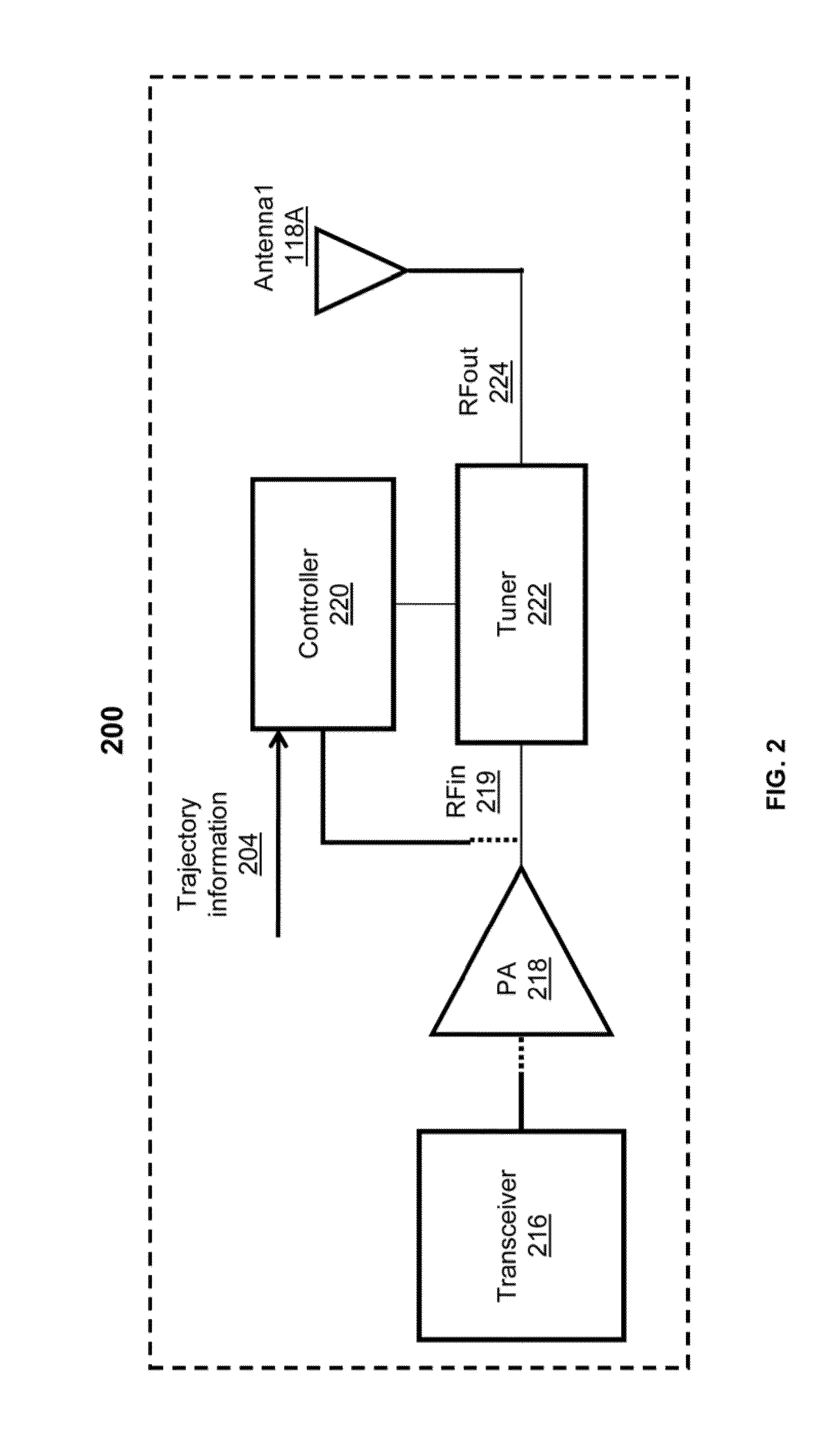
[0013]The illustrative embodiments provide a method, transceiver integrated circuit (IC), and communications device for generating antenna tuning states to adjust a detected signal level towards a preset, given value, where the antenna tuning states are derived from a pre-established trajectory of tuning states. A tuning state generation (TSG) controller and / or TSG logic executing on a processor determines whether a detected signal level matches the preset, given value. If the detected signal level fails to match the given value, the TSG controller determines which operating condition of one or more pre-identified operating conditions best matches the current operating condition. Each operating condition supported by the device is respectively associated with a specific pre-established trajectory of tuning states. In response to determining that a particular pre-identified operating condition best matches the current operating condition, the controller selects the initial preset tun...


PUM


Abstract

A method, transceiver integrated circuit (IC), and communications device for generating antenna tuning states derived from a pre-established trajectory of tuning states to adjust a detected signal level towards a preset, given value. A tuning state generation (TSG) controller determines whether a detected signal level matches a given value. If the detected signal level does not match the given value, the TSG controller selects an initial preset tuning state from a pre-established trajectory corresponding to a pre-identified operating condition that best matches a current operating condition. The TSG logic forwards the initial preset tuning state to the antenna tuner to trigger impedance transformation. Following generation of the initial preset tuning state, the controller receives an updated detected signal level. If the updated detected signal level fails to match the given value, the controller generates an incremental tuning state that is interpolated between the initial and a final preset tuning states.

Description

BACKGROUND[0001]1. Technical Field[0002]The present invention relates in general to wireless communications devices and in particular to antenna tuning in wireless communications devices.[0003]2. Description of the Related Art[0004]As the number of mode combinations, features and functions in wireless communications devices increase, providing high quality communications with these devices becomes increasingly difficult. In addition, today's wireless communications devices are integrated with many applications, including gaming applications, and other electronic functionality, such as the provision of a camera, for example. While these applications and electronic functions are being used, ensuring that communications signals have a clear, unobstructed path to and from the antenna presents a unique challenge. The communications challenges further increase as a result of the wide range of transmission requirements associated with the various communications modes that the device is exp...

Claims


Application Information

Patent Timeline
Patent Type & Authority Patents(United States)
IPC IPC(8): H04B1/18
CPCH04B1/0458H04B1/18
Inventor BLACK, GREGORY R.ALBERTH, WILLIAM P.
Owner GOOGLE TECHNOLOGY HOLDINGS LLC
Learn More