Wake-up radio system
a radio system and wake-up technology, applied in power management, instruments, high-level techniques, etc., can solve the problems of difficult simultaneous achievement of low latency and low power
- Summary
- Abstract
- Description
- Claims
- Application Information
AI Technical Summary
Problems solved by technology
Method used
Image
Examples
first embodiment
A. First Embodiment
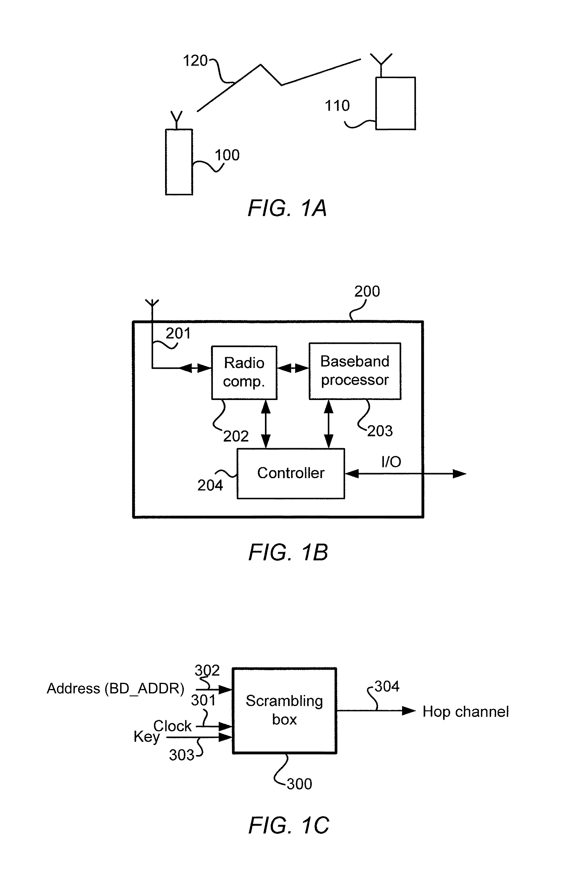
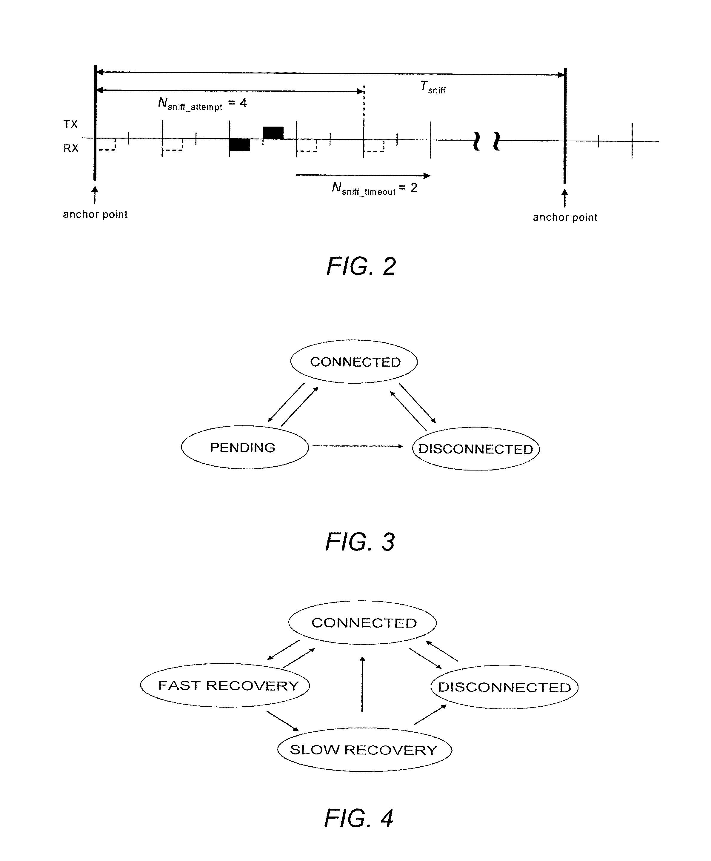
[0057]During fast recovery, the time elapsed since the previous or last synchronization between master unit 100 and slave unit 110 is still sufficiently small (a couple of minutes up to e.g. maximum 30 minutes) to be able to predict the timing in the both units 100, 110 (see FIG. 1). The former slave unit 110 (e.g. a headset or a watch) enters a recovery scan state; the former master unit 100 (e.g. a mobile phone) enters a recovery page state. Important to mention is that both these states may be low duty cycle states (in contrast to the conventional page state in Bluetooth).
[0058]1. Fast Recovery Scan
[0059]When a loss of link 120 (see FIG. 1) has been detected, the former slave unit 110 enters the fast recovery scan state. The initial timing of the scan window may be based on the anchor point timing experienced during sniff. That is, the center of the scan window may be placed at the former anchor point, see FIG. 5 which illustrates a timing diagram of the fast r...
second embodiment
B. Second Embodiment
[0091]During fast recovery, the time elapsed since the previous or last synchronization is still sufficiently small (a couple of minutes up to e.g. maximum 30 minutes) to be able to predict the timing in the both units 100, 110 (see FIG. 1). The former slave unit 110 (e.g. a headset or a watch) enters a recovery scan state; the former master unit 100 (e.g. a mobile phone) enters a recovery page state. Important to mention is that both these states are low duty cycle states (in contrast to the conventional page state in Bluetooth).
[0092]1. Fast Recovery Scan
[0093]When a loss of link 120 (see FIG. 1) has been detected, the former slave unit 110 enters the fast recovery scan state. The initial timing of the scan window may be based on the anchor point timing experienced during sniff. That is, the center of the scan window may be placed at the former anchor point, see FIG. 14 which illustrates a timing diagram of the fast recovery scan window. The scan window may hav...
PUM
 Abstract
Description
Claims
Application Information
 - R&D
- Intellectual Property
- Life Sciences
- Materials
- Tech Scout
- Unparalleled Data Quality
- Higher Quality Content
- 60% Fewer Hallucinations
Browse by: Latest US Patents, China's latest patents, Technical Efficacy Thesaurus, Application Domain, Technology Topic, Popular Technical Reports.
© 2025 PatSnap. All rights reserved.Legal|Privacy policy|Modern Slavery Act Transparency Statement|Sitemap|About US| Contact US: help@patsnap.com


