Non-invasive tranducers for ultrasonic transit time flow meters

Active Publication Date: 2014-05-06
STRAIN MEASUREMENT DEVICES
View PDF9 Cites 82 Cited by
  • Summary
  • Abstract
  • Description
  • Claims
  • Application Information

AI Technical Summary

Benefits of technology

[0010]It is an advantage of the present invention that the ultrasonic flow meter can accommodate flexible tubes that may be made readily disposable.
[0011]It is another advantage of the present invention that flexible tubing commonly used in the medical field may be used.
[0012]It is a feature of the present invention that a partial ring transduce

Problems solved by technology

While these ultrasonic flow meters have adequately measured fluid flow they have been difficult to use in many applications, particularly where different sizes of tubes are used and where there is a need to frequently replace tubes.
While these devic

Method used


Image

  • Non-invasive tranducers for ultrasonic transit time flow meters
  • Non-invasive tranducers for ultrasonic transit time flow meters
  • Non-invasive tranducers for ultrasonic transit time flow meters

Examples


Embodiment Construction

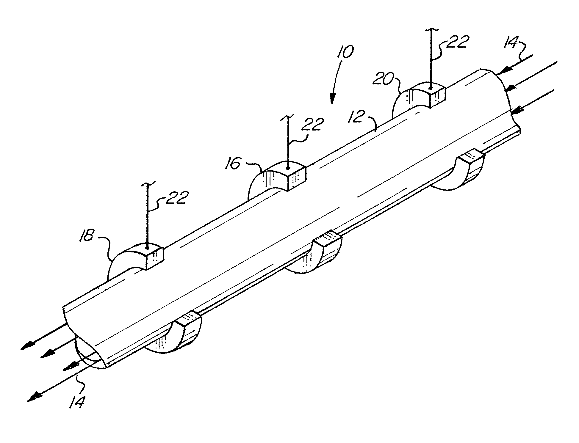
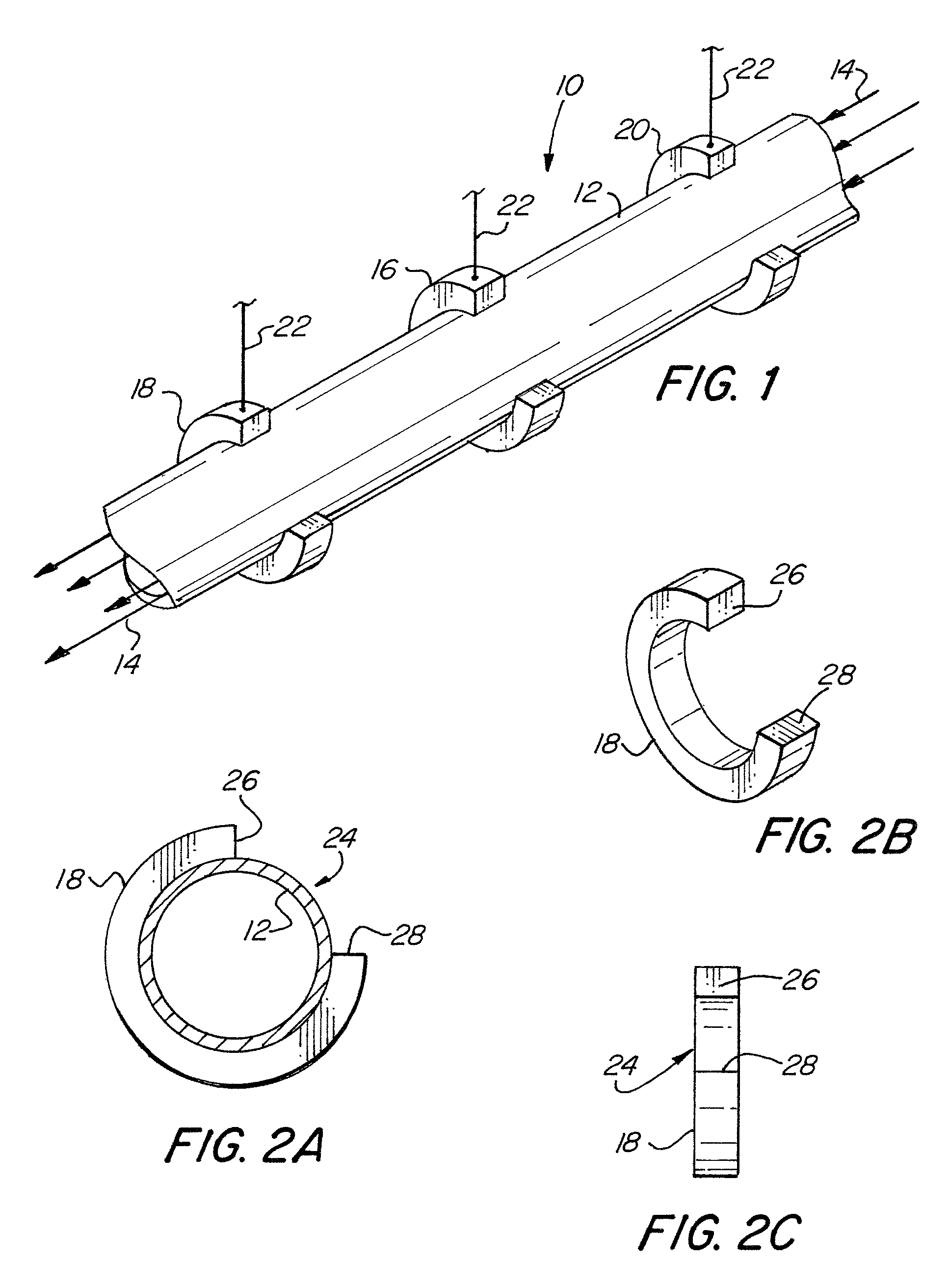
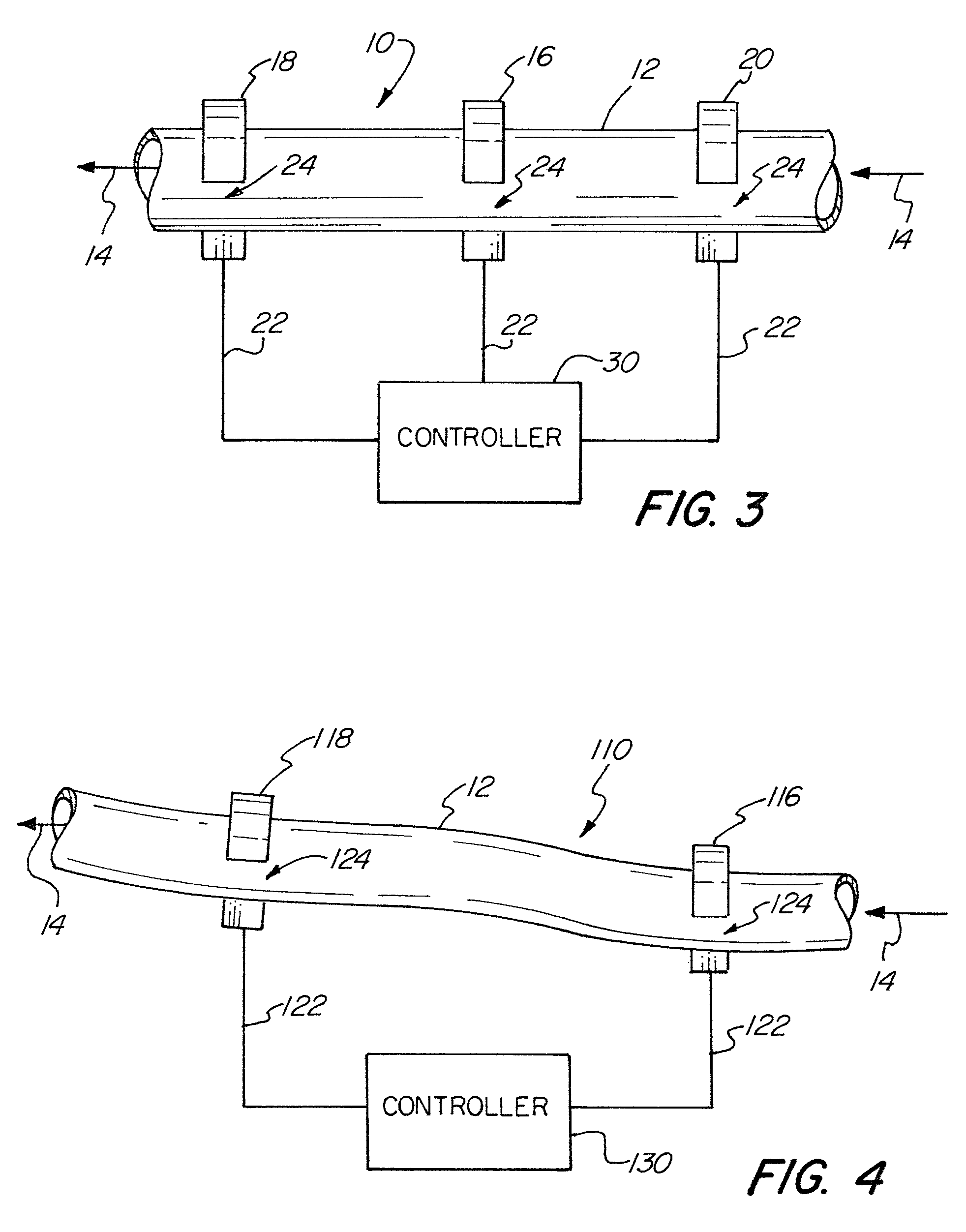
[0030]FIG. 1 is a perspective view illustrating an ultrasonic flow meter of the present invention. The ultrasonic flow meter 10 holds a soft or flexible tube 12 having a fluid flow moving in the direction of arrows 14. The tube 12 may be made of polyvinyl chloride or PVC, silicone, or other soft or flexible material. A plurality of partial ring transducers 16, 18 and 20 are placed around the tube 12. Each of the plurality of partial ring transducers are coupled through a wire or conductor 22 to a controller containing electronics, not shown, for controlling the transmission and reception from the plurality of transducers 16, 18 and 20. The center partial ring transducer 16 may act as a transmitter with the upstream partial ring transducer 18 and the downstream partial ring transducer 20 acting as receivers. The plurality of partial ring transducers may be made of a piezoelectric material, such as lead zirconate titanate or PZT, or other materials with piezoelectric properties.

[0031]...


PUM


Abstract

An ultrasonic flow meter permitting easy insertion and removal of a tube or conduit. A partial ring transducer or partial cylinder transducer is used to permit easy insertion and removal of a flexible tube in an ultrasonic flow meter for measuring fluid flow. In another embodiment a split ring or split cylinder transducer is used to facilitate easy removal and insertion of a tube or conduit in which fluid flow is to be measured. In another embodiment a clamping system is used to securely hold and couple a tube or conduit within the ultrasonic flow meter system. The present invention is conveniently adapted to hold flexible tubes and in particular disposable flexible tubes often used in the medical industry.

Description

FIELD OF THE INVENTION[0001]The present invention relates in general to ultrasonic flow meters used to measure fluid flow in tubes or conduits, and more particularly to an ultrasonic transducer system permitting easy insertion of flexible tubes.BACKGROUND OF THE INVENTION[0002]The use of ultrasonic transducers to measure fluid flow is well-known. One such flow meter is disclosed in U.S. Pat. No. 5,594,181 entitled “Ultrasonic Flow Meter” and issuing to Stange on Jan. 14, 1997. Therein disclosed is an ultrasonic flow meter having two ring-shaped piezoelectric transducers with one operating as an ultrasonic transmitter and the other one as an ultrasonic receiver. The two ring-shaped piezoelectric transducers are embedded into the wall of a pipe.[0003]Another ultrasonic flow meter is disclosed in U.S. Pat. No. 5,974,897 entitled “Ultrasonic Flow Meter” and issuing to Koyano et al on Nov. 2, 1999. Therein disclosed is an ultrasonic flow meter having three ring-shaped oscillators dispose...

Claims


Application Information

Patent Timeline
IPC IPC(8): G01F1/66
CPCG01F1/66G01F1/662
Inventor LIU, LINGLIJACKSON, FREDERICK E.
Owner STRAIN MEASUREMENT DEVICES
Why Eureka
Try Eureka