Edge connector

a connector and edge technology, applied in the field of electric connectors, can solve the problems of aggravated problems such as high speed or high frequency signal transmission, impedance, crosstalk, attenuation, etc., and achieve the effect of reducing the number of pin retraction or inappropriate bending, and reducing the density of pins

Active Publication Date: 2014-05-06
FCI ASIA PTE LTD
View PDF22 Cites 10 Cited by
  • Summary
  • Abstract
  • Description
  • Claims
  • Application Information

AI Technical Summary

Benefits of technology

[0009]Another purpose of the present invention is to provide a connector with high density pins which can be press-fitted in an assembled state and that pin retraction or inappropriate bending can be greatly reduced when the terminals of the press-fit connector are pressed into the through holes on a motherboard.

Problems solved by technology

These changes, however, aggravates the problems related to signal transmission with high speed or high frequency, such as impedance, cross talk, propagation delay, attenuation, skew and rise time degradation.
Therefore, obtaining desired performance of the system with a appropriate connectors has become a challenge to the industry.

Method used


Image

  • Edge connector
  • Edge connector
  • Edge connector

Examples


Embodiment Construction

[0023]Preferred embodiments of the present invention will be illustrated with reference to the accompanying drawings, and reference numerals in the drawings are used to indicate corresponding elements.

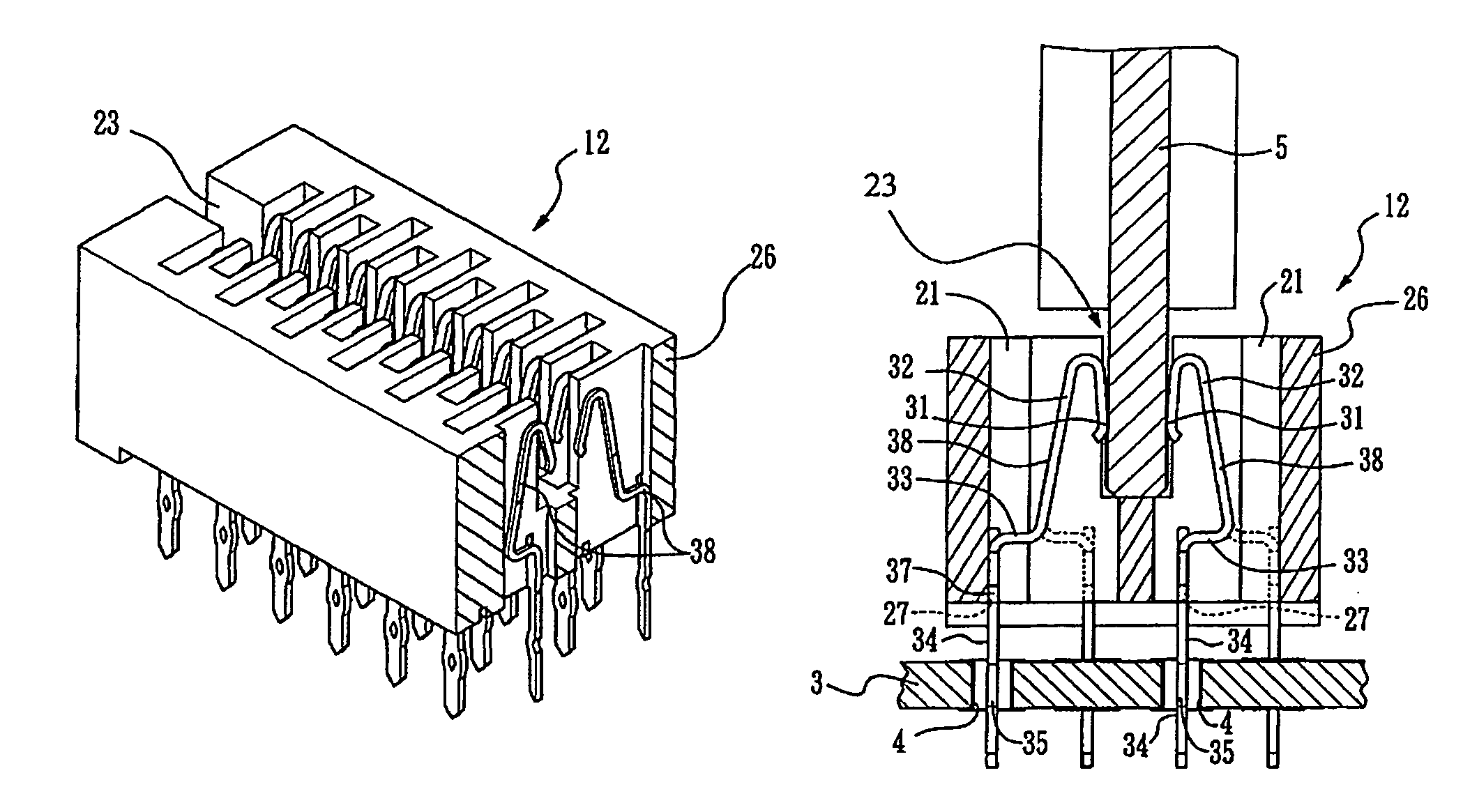
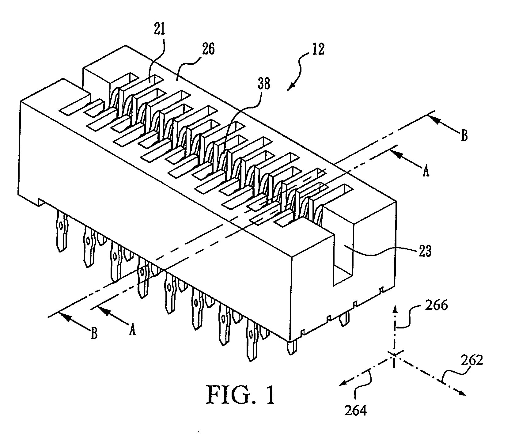
[0024]As shown in FIG. 1, a high speed connector 12 is generally of an elongated rectangular shape, and includes a housing 26 molded from electrically insulative material, with a plurality of compartments 21 formed therein and a long slot 23 in a central portion. The compartments 21 are located on two sides of the slot 23 and each compartment has a conductor 38 retained therein. For the purpose of illustration of the orientation of housing 26 and conductors 38, housing 26 defines a longitudinal or length direction 262, a lateral or width direction 264, and an elevation or height direction 266.

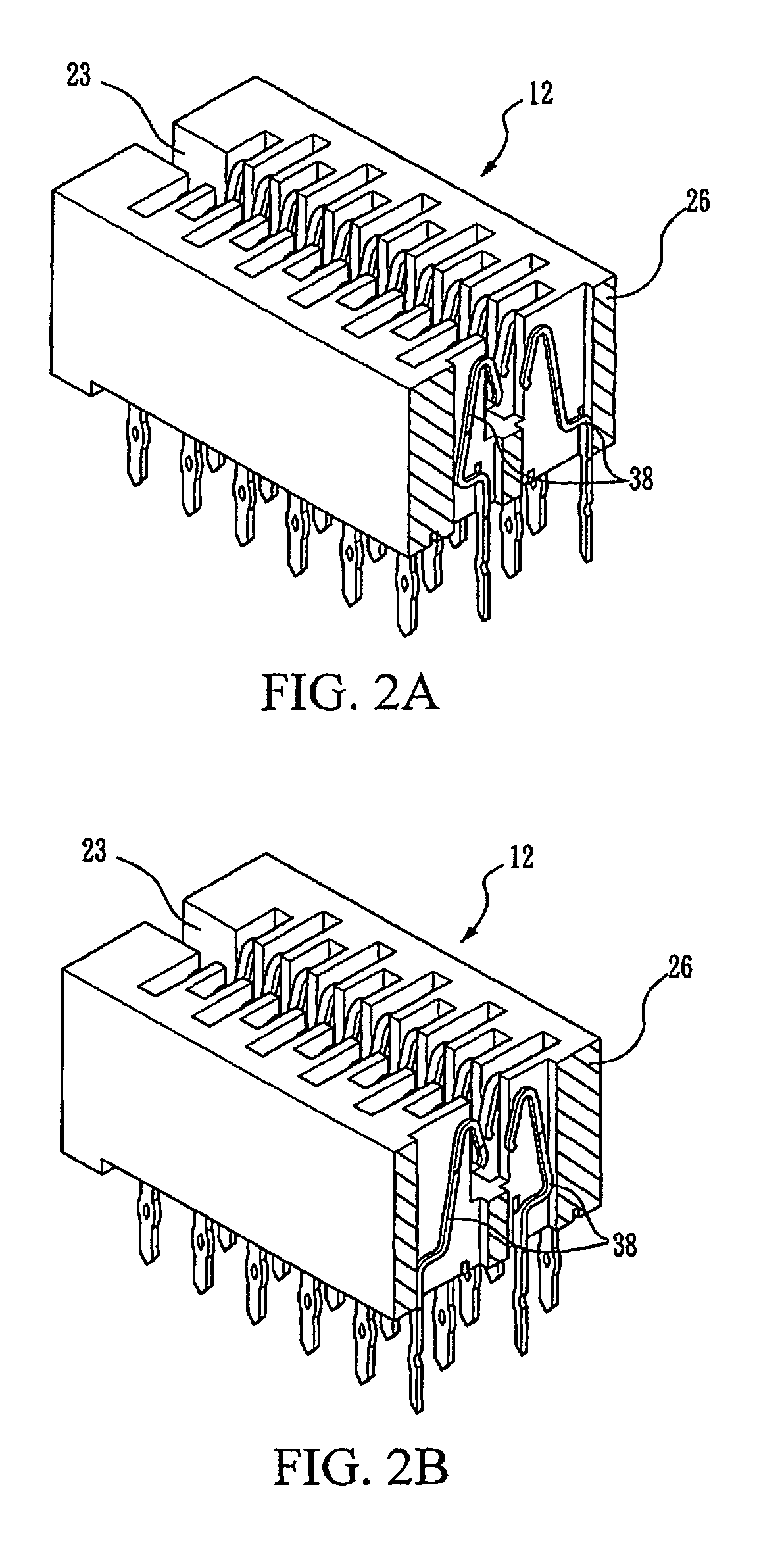
[0025]FIG. 2A is a perspective cross-sectional view of a connector shown in FIG. 1, taken along line A-A in FIG. 1, and FIG. 2B is a perspective cross-sectional view taken along line B-B in FIG. 1...


PUM


Abstract

An edge connector for transmitting signals at a high frequency, for example in a system environment with a frequency higher than 2.0 GHz or 3.0 GHz, is provided. The connector includes a housing and at least a first and a second conductors disposed in the housing. Each conductor has a contact portion and a terminal portion, and each contact portion form a contact surface. The at least first and second conductors are disposed in the housing in such a manner that, both the contact surfaces face a first direction, the terminal portion of the first conductor is offset from the contact portion of the first conductor along the first direction, and the terminal portion of the second conductor is offset from the contact portion of the second conductor along a second direction which is opposite to the first direction.

Description

FIELD OF THE INVENTION[0001]The present invention relates to an electrical connector, and more particularly to an edge connector for transmitting signals at a high frequency for example, higher than 400 MHz or even higher than 2.0 GHz.BACKGROUND OF THE INVENTION[0002]In a computer or telecommunication system, an interface connecting to the external is generally designed as a bus for transmitting various data. The hardware interface is fabricated to be an expandable slot, i.e., a so-called edge connector. The slot is attached to a motherboard. A modular daughter board, such as an interface card or memory card, can be inserted into the slot, so as form a connection interface. The edge connector generally connects a motherboard and a daughter board in the following manner. Through holes for connecting the connectors are formed on the motherboard. A conductive metal layer is plated to the inner surface and the periphery of the through holes, and the circuits to be connected to the bus o...

Claims


Application Information

Patent Timeline
Patent Type & Authority Patents(United States)
IPC IPC(8): H01R24/00H01R12/71
CPCH01R12/716H01R12/82
Inventor WU, LEONCHIU, RICHARD
Owner FCI ASIA PTE LTD
Why Eureka
Try Eureka