
Fuel cutoff valves

a technology of fuel cutoff valve and float valve body, which is applied in the direction of valve operating means/releasing devices, functional valve types, containers, etc., can solve the problems of too weak spring force of valve spring and inability to elevate the float valve body, and achieve the effect of improving the discharging efficiency of liquid

Active Publication Date: 2014-05-13
AISAN IND CO LTD
View PDF19 Cites 10 Cited by
  • Summary
  • Abstract
  • Description
  • Claims
  • Application Information

AI Technical Summary

Benefits of technology

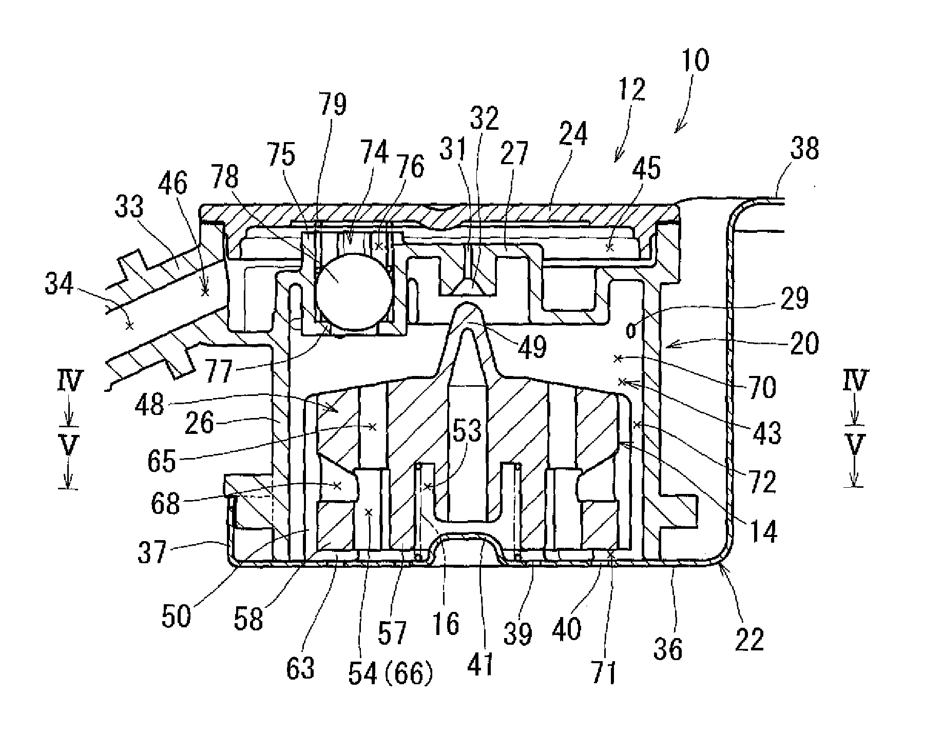
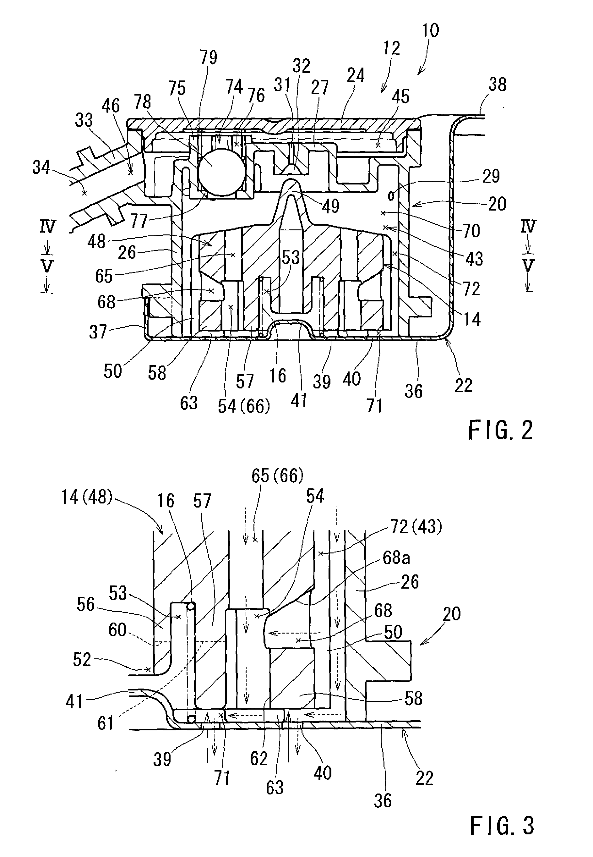
[0011]In accordance with this aspect, when discharging liquid from the float chamber, the liquid between the outer surface of the float and an inwardly facing surface of the housing can easily flow into the first passage via the second passage. Thus, it is able to prevent the fuel from remaining in such space and thus to improve discharging efficiency of the liquid.

Problems solved by technology

However, spring force of the valve spring 105 is too weak to elevate the float valve body 103 by oneself.

Method used


Image

  • Fuel cutoff valves
  • Fuel cutoff valves
  • Fuel cutoff valves

Examples


Embodiment Construction

[0027]Each of the additional features and teachings disclosed above and below may be utilized separately or in conjunction with other features and teachings to provide improved fuel cutoff valves. Representative examples, which examples utilize many of these additional features and teachings both separately and in conjunction with one another, will now be described in detail with reference to the attached drawings. This detailed description is merely intended to teach a person of skill in the art further details for practicing preferred aspects of the present teachings and is not intended to limit the scope of the invention. Only the claims define the scope of the claimed invention. Therefore, combinations of features and steps disclosed in the following detailed description may not be necessary to practice the invention in the broadest sense, and are instead taught merely to particularly describe representative examples of the invention. Moreover, various features of the representa...


PUM


Abstract

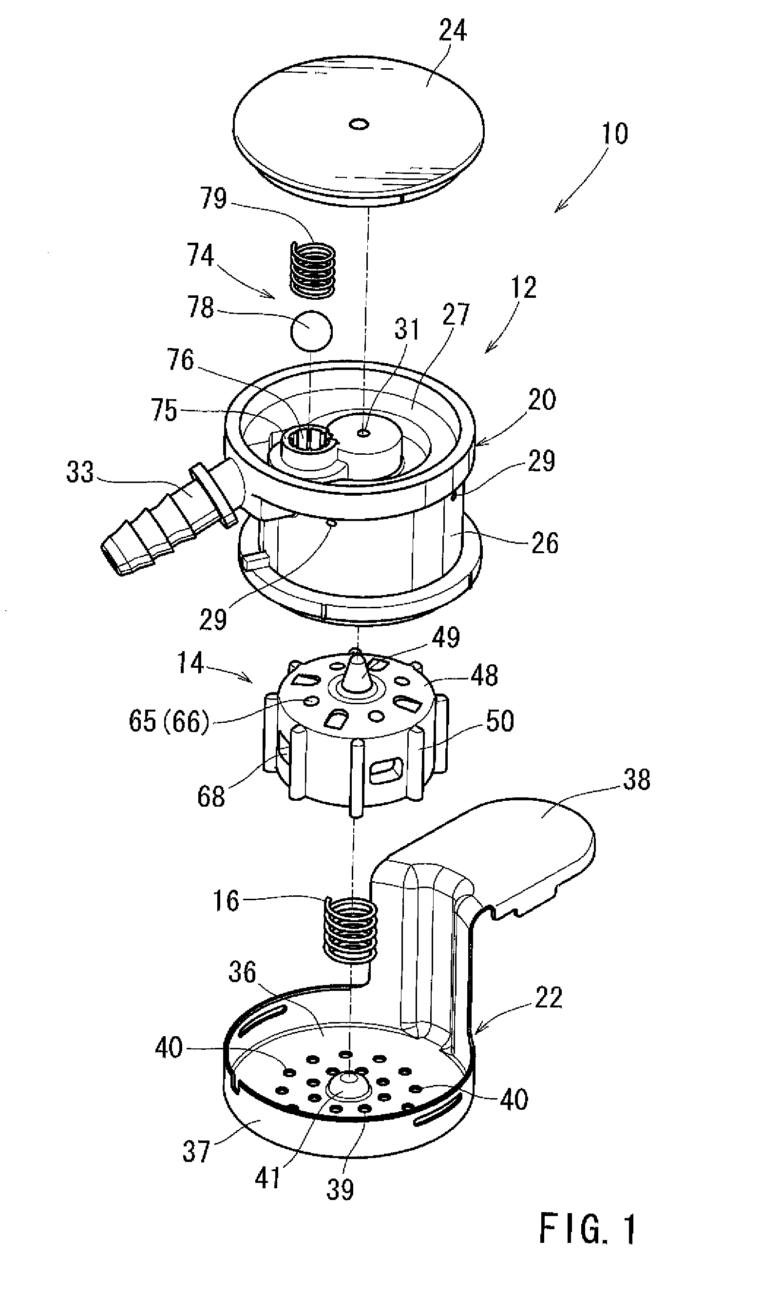
A fuel cutoff valve has a housing defining therein a float chamber and a float disposed in the float chamber. The housing defines a connection passage positioned above the float chamber and fluidly connecting the float chamber with outside of the housing and a hole positioned below the fluid chamber fluidly connecting the float chamber with outside of the housing. The float has a valve part that is configured to close the connection passage and defines therein a first passage passing through the float in a vertical direction and a second passage extending from a part of the first passage to an outer surface of the float in a substantial horizontal direction.

Description

CROSS-REFERENCES TO RELATED APPLICATIONS[0001]This application claims priority to Japanese patent application serial number 2010-146161, the contents of which are incorporated herein by reference.BACKGROUND OF THE INVENTION[0002]1. Field of the Invention[0003]This disclosure relates to fuel cutoff valves each attached to a fuel tank of a vehicle such as gas vehicle.[0004]2. Description of the Related Art[0005]A vehicle such as gasoline vehicle has a fuel tank provided with a fuel cutoff valve. The fuel cutoff valve allows fluid communication between an inner space of the fuel tank and outside of the fuel tank (for example, adsorbent canister) in a normal condition, and prevents fuel from flowing outside the fuel tank in conditions that the vehicle is inclined or overturns, etc.[0006]Japanese Laid-Open Patent Publication No. 2005-194957 discloses a conventional fuel cutoff valve as shown in FIGS. 13 an 14. FIG. 13 shows a cross-sectional view of the fuel cutoff valve in an open state...

Claims


Application Information

Patent Timeline
Patent Type & Authority Patents(United States)
IPC IPC(8): F16K24/04
CPCF16K24/044Y10T137/7358Y10T137/0874Y10T137/3099
Inventor YASUDA, YOSHIHIROHARUTA, KAZUMIKATO, TAKASHI
Owner AISAN IND CO LTD
Learn More