Table feeder

a technology for table feeders and feeders, applied in the direction of instruments, movable measuring chambers, volume meters, etc., can solve the problems of overloading the drive device that rotates the rotary vanes, and achieve the effects of low fluidity, low load, and efficient discharg

Inactive Publication Date: 2011-02-10
TSUKASA
View PDF8 Cites 20 Cited by
  • Summary
  • Abstract
  • Description
  • Claims
  • Application Information

AI Technical Summary

Benefits of technology

[0008]There is no structural feature that facilitates the release of the pressure that is built up in the particulate material in this region, and the rotation power of the rotary vanes may be lowered under the force of the built-up pressure. The drive device for the rotary vanes must thus be designed to have a sufficiently large power capacity. A thick bottom plate and a large size drive device are required to provide sufficient resistance against the particulate materials pressure. Particulate material with low fluidity, for example, crystalline materials such as granulated sugar or bran with a significant oil content, may readily aggregate. Aggregation of the particulate material interferes with the smooth rotation of the rotary vanes and may overload the drive device that rotates the rotary vanes.
[0013]The discharger is preferably located at the deepest position of the particulate material processing vessel. One typical example of the deepest position is a bottom of a recess formed in the bottom assembly. The recess is a boundary between the bottom plate and the side plate and is preferably curved. To enhance the discharge efficiency, the rotation trajectory of the end of the rotary vane preferably passes through an opening of the discharger. In applications with a bottom plate in an inclined orientation, the particulate material gathers at the discharger by means of gravitational collapse of the particulate material and under the action of the rotary vane. The inclined orientation of the bottom plate also induces the wash water to flow toward the discharger, thereby facilitates cleaning.
[0017]In the table feeder according to the above aspect of the invention, the particulate material is fed onto the upper face of the cone, and there is a gap formed in a lower space below the cone. The primary volume through which the particulate material moves under the action of the rotary vane is restricted to a peripheral area of the bottom plate (a donut-shaped area in the planar view). As the rotary vane moves the particulate material, the particulate material may be released through the gap. This arrangement desirably lowers the load applied to the rotary vane and enables the particulate material, even that having a low fluidity, to be efficiently discharged via the discharger by means of the rotary vane.
[0018]In the table feeder of the above embodiment having a through-hole and a scraping element, if particulate material with a low fluidity aggregates in the particulate material processing vessel, the scraping element may cut and crush the particulate material that is accumulated or aggregated on the upper face of the cone, thereby enabling the crushed particulate material to flow down via the through-hole to the gap formed below the cone. This arrangement assures the smooth discharge of particulate material having a low fluidity via the discharger.

Problems solved by technology

Aggregation of the particulate material interferes with the smooth rotation of the rotary vanes and may overload the drive device that rotates the rotary vanes.

Method used


Image

  • Table feeder
  • Table feeder
  • Table feeder

Examples


Embodiment Construction

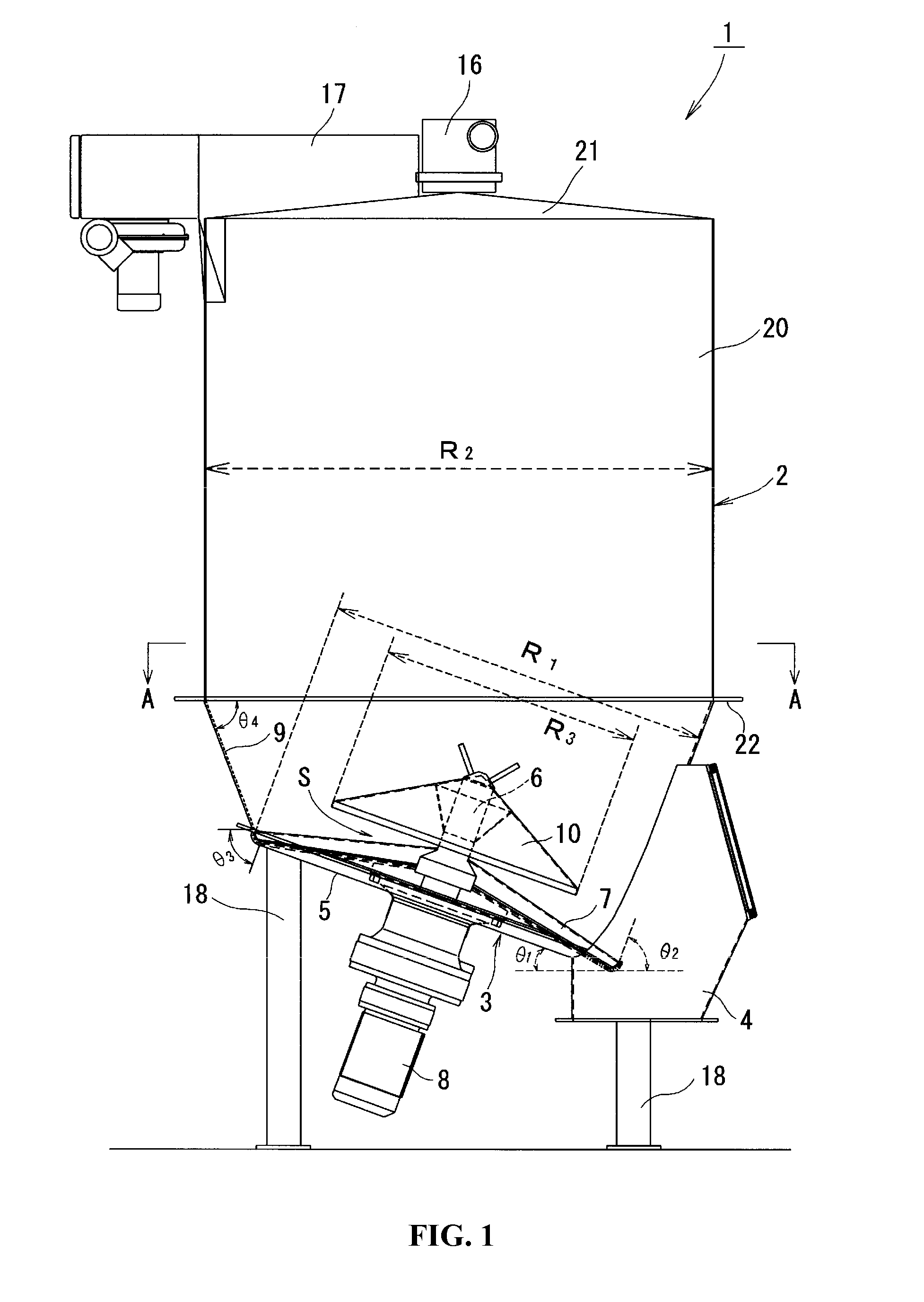
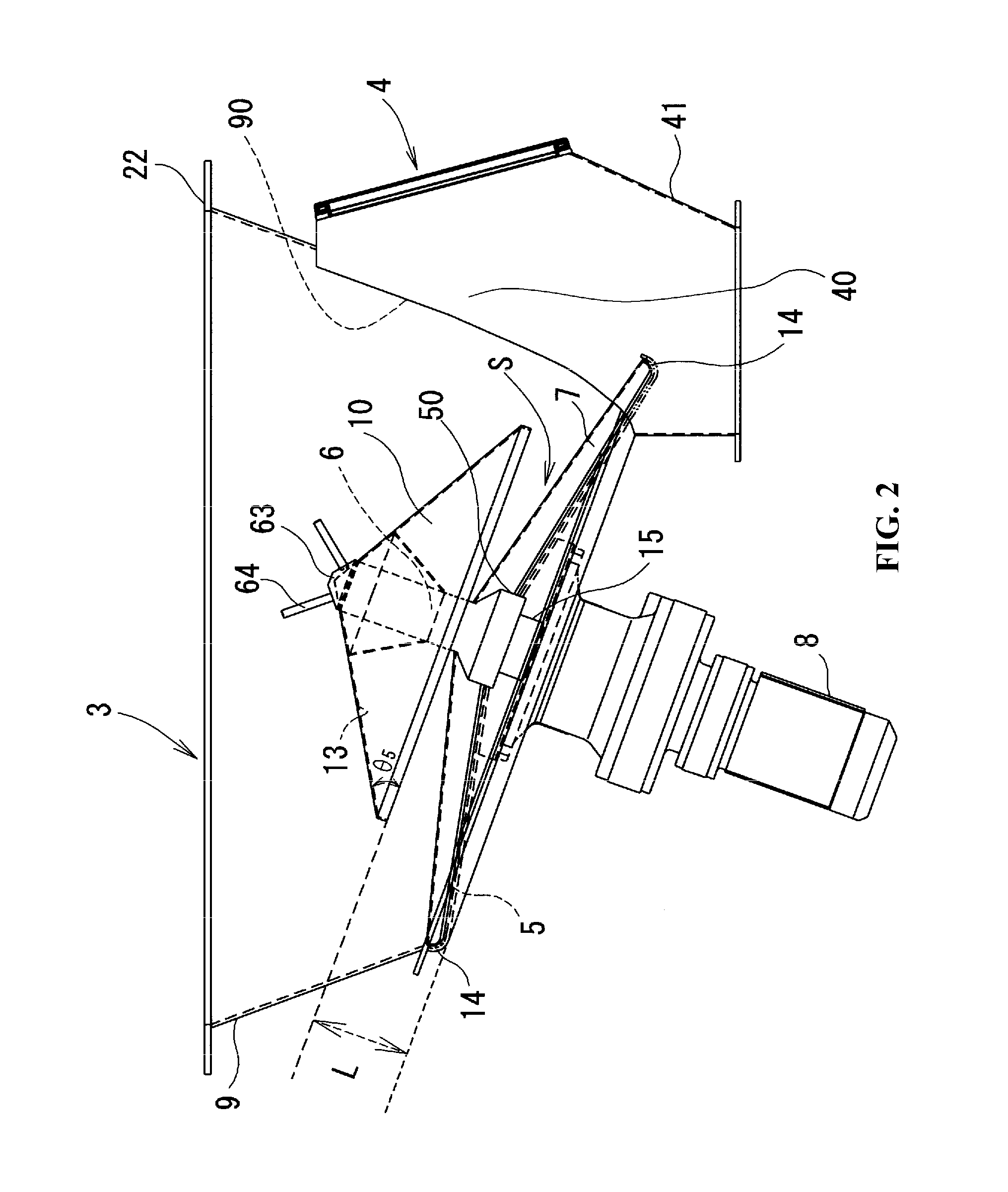
[0036]A table feeder 1 according to a first embodiment of the invention is described below with reference to the accompanied drawings. As shown in FIGS. 1 through 4, the table feeder 1 includes a bottom assembly 3 of a particulate material processing vessel 2, a discharger 4 formed in the bottom assembly 3 to allow for discharge of a particulate material P (FIG. 4) kept in the particulate material processing vessel 2, a bottom plate 5 provided in the bottom assembly 3, a rotating shaft 6 perpendicularly attached to a main face 5a of the bottom plate 5 to rotate on the center of the bottom plate 5, rotary vanes 7 rotated on the bottom plate 5 by the rotating shaft 6 to discharge the particulate material P kept in the particulate material processing vessel 2 via the discharger 4, and a drive device 8 provided to drive and rotate the rotary vanes 7. The bottom assembly 3 has the bottom plate 5 and a side plate 9 connecting with and surrounding the bottom plate 5.

[0037]A cone 10 having ...


PUM


Abstract

A table feeder 1 has a bottom assembly 3 of a particulate material processing vessel 2, a discharger 4 provided in the bottom assembly 3 to discharge a particulate material P kept in the vessel 2, a bottom plate 5 included in the bottom assembly 3, a rotating shaft 6 provided vertically to a main face 5a of the bottom plate 5 to rotate on the center of the bottom plate 5, rotary vanes 7 to discharge the particulate material P kept in the particulate material processing vessel 2 via the discharger 4 and a drive device 8 configured to drive and rotate the rotary vanes 7. A cone 10 having a smaller diameter than a diameter of the rotary vanes 7 is provided in the space above the rotary vanes 7 coaxially with the rotary vanes7 to extend over a central area of the rotary vane 7.

Description

CROSS-REFERENCE TO RELATED APPLICATIONS[0001]This application is a continuation of International Patent Application No. PCT / JP2009 / 002974, with an international filing date of Jun. 27, 2009, designating the United States, now pending, and claims foreign priority benefits to Japanese Patent Application No. 2008-172430, filed Jul. 1, 2008. The contents of all of these specifications, including any intervening amendments thereto, are incorporated herein by reference.BACKGROUND OF THE INVENTION[0002]1. Field of the Invention[0003]This invention relates to a table feeder disposed on a bottom of a particulate material processing vessel for keeping therein a particulate material, such as a food product, a chemical product, a pharmaceutical product, a cosmetic product, a feedstuff, or a fertilizer.[0004]2. Description of the Related Art[0005]A table feeder is conventionally fastened to a bottom assembly of a particulate material processing vessel for keeping a particulate material therein. ...

Claims


Application Information

Patent Timeline
Patent Type & Authority Applications(United States)
IPC IPC(8): G01F11/20
CPCB65D88/68B65G65/4836B65G65/4827
Inventor KATO, FUMIO
Owner TSUKASA
Why Eureka
Try Eureka