Image forming device

a technology of image forming device and forming surface, which is applied in the direction of instruments, electrographic process equipment, optics, etc., can solve the problems of lowering lowering the quality of image formed by the image forming device, and affecting the detection accuracy of detection patterns

Active Publication Date: 2014-05-13
BROTHER KOGYO KK
View PDF25 Cites 2 Cited by
  • Summary
  • Abstract
  • Description
  • Claims
  • Application Information

AI Technical Summary

Benefits of technology

[0010]Aspects of the present invention are advantageous to provide one or more improved techniques for an image forming device having process cartridges and an endless belt, which techniques make it possible to keep clean a detection surface of a detection sensor for reading each detection pattern formed on the endless belt.

Problems solved by technology

As described above, since the detection surface of the optical sensor faces the endless belt, when toner used for the formation of the image or the detection pattern image is splashed, the detection surface is likely to be contaminated by the splashed toner.
Such a contaminated detection surface might lead to a lowered level of detection accuracy for detection of the detection patterns and in a lowered level of quality of the image formed by the image forming device.
In this case, however, favorable image quality might not certainly be assured as a moment to clean the detection surface is determined by the user.
Further, the user could not clean the detection surface on user's own due to a problem concerning a positional relationship between the optical sensor and a different component.

Method used


Image

  • Image forming device
  • Image forming device
  • Image forming device

Examples


first embodiment

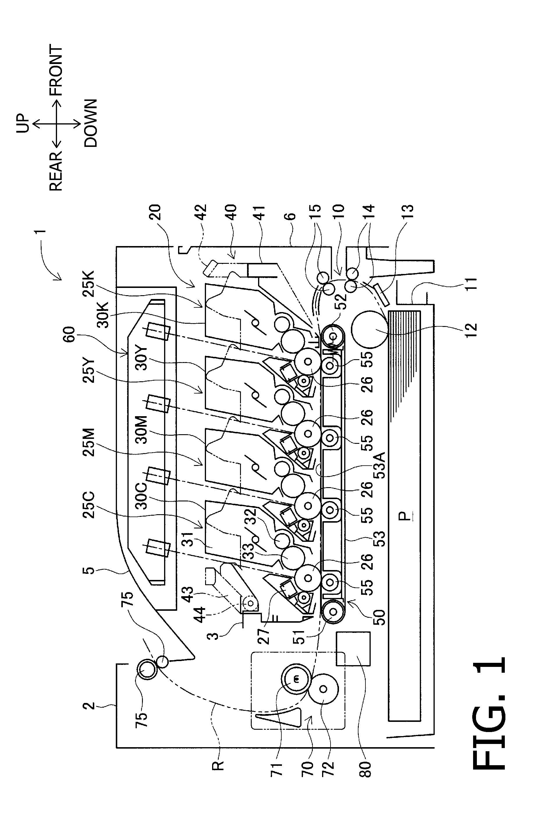
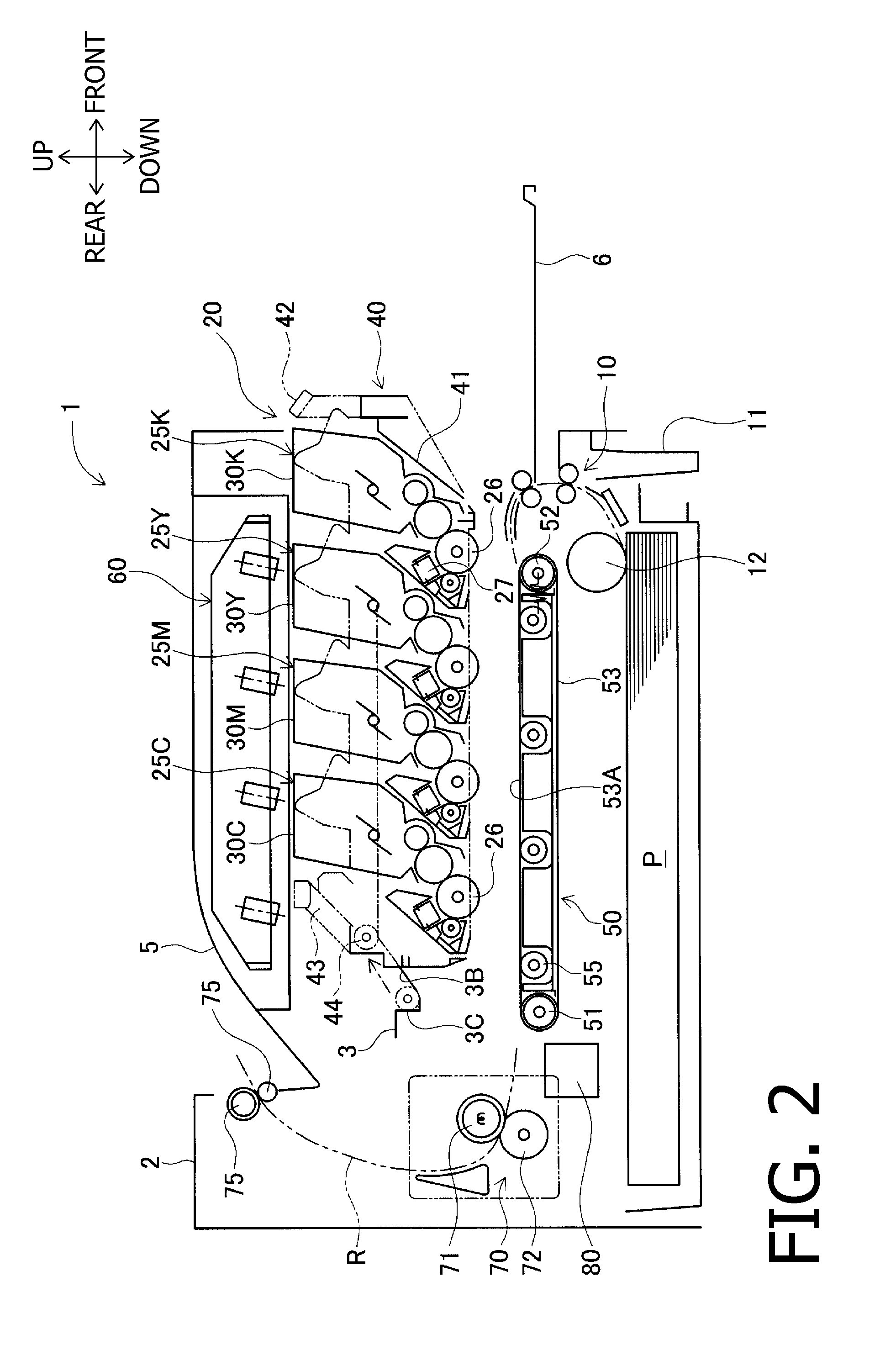
[0022]Hereinafter, a laser printer 1 of a first embodiment according to aspects of the present invention will be described with reference to FIGS. 1 to 4. In the following description, an up-to-down direction (i.e., the vertical direction) and a front-to-rear direction (and a left-to-right direction) of the laser printer 1 will be defined as depicted in the relevant drawings for the sake of easy understanding of a relative positional relationship among elements included in the laser printer 1. The laser printer 1 is a color laser printer configured to form a multicolor image on a sheet P using an electrophotographic technique.

[0023]As shown in FIG. 1, the laser printer 1 includes a substantially box-shaped main body housing 2. Further, the laser printer 1 includes a feeding unit 10, an image forming unit 20, a conveying unit 50, a scanning unit 60, a fixing unit 70, and a registration sensor unit 80, all of which are housed in the main body housing 2. The image forming unit 20 is di...

second embodiment

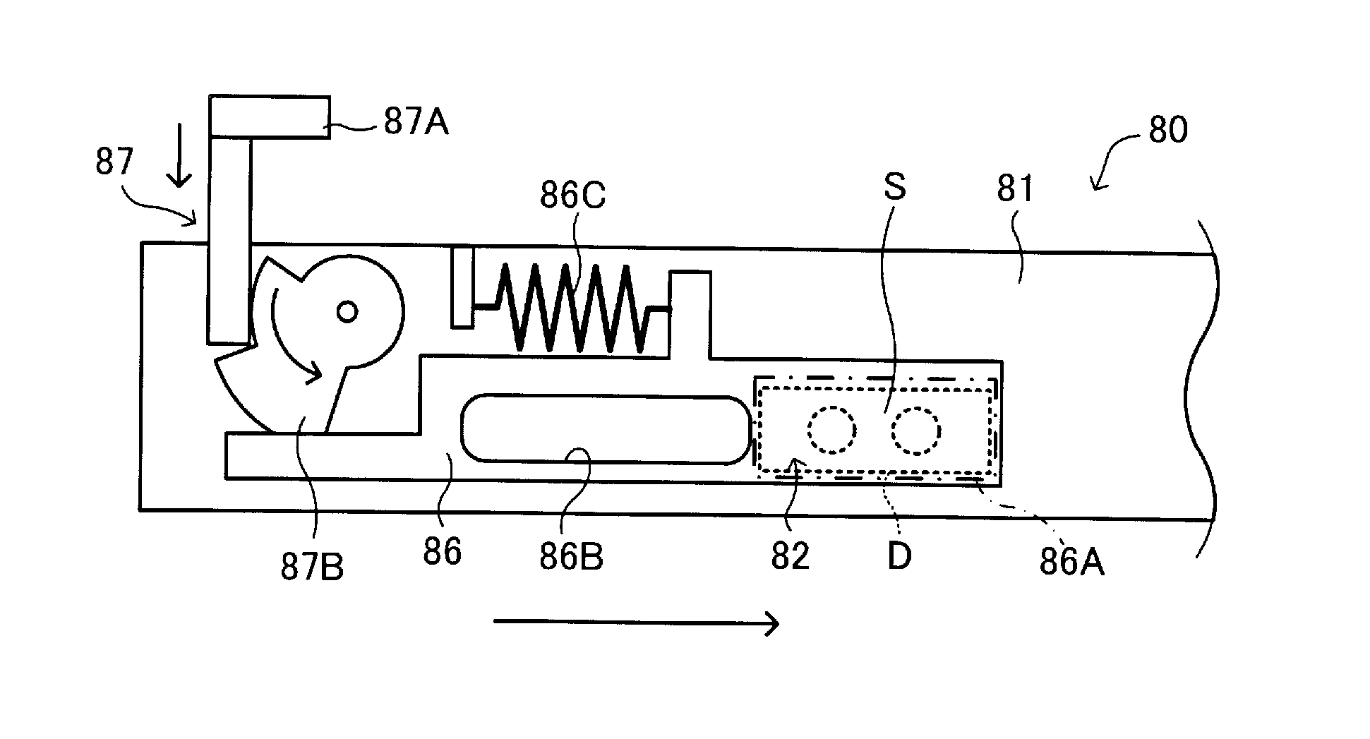
[0081]Subsequently, a second embodiment will be described with reference to FIG. 10. In the second embodiment, the basic configuration of the laser printer 1 is the same as that in the first embodiment. Therefore, an explanation about the basic configuration of the laser printer 1 will be omitted. The second embodiment is different from the first embodiment with respect to the configuration of the registration sensor unit 80. Hence, in the following description, a registration sensor unit 80 of the second embodiment will be described.

[0082]FIGS. 10A and 10B are front views showing a portion around a right end of the registration sensor unit 80 in the second embodiment. FIG. 10C is a top view of the registration sensor unit 80 in the second embodiment. A configuration of a portion around a left end of the registration sensor unit 80 is substantially the same as that around the right end, except for left-right reversal. Thus, in the following description, a portion around the right en...


PUM


Abstract

An image forming device is provided, which includes an interlocking mechanism that causes a cleaning unit to clean with a cleaning surface thereof a detection surface of a detection sensor for reading each detection pattern formed on an outer surface of a sheet-feeding endless belt, in conjunction with movement of a drawer, which holds a plurality of process cartridges, between an attachment position where a photoconductive drum included in each process cartridge faces an up-facing side of the outer surface of the endless belt and a replacement position where at least one of the process cartridges is outside a main body housing of the image forming device.

Description

CROSS-REFERENCE TO RELATED APPLICATION[0001]This application claims priority under 35 U.S.C. §119 from Japanese Patent Application No. 2010-219208 filed on Sep. 29, 2010. The entire subject matter of the application is incorporated herein by reference.BACKGROUND[0002]1. Technical Field[0003]The following description relates to one or more image forming devices that include a belt unit having an endless belt, a plurality of process cartridges, arranged along the belt unit, each of which contains therein a specific color of recording agent used for color image formation, and a detection sensor configured to optically read a detection pattern formed on the endless belt with each recording agent.[0004]2. Related Art[0005]So far, as an image forming device that forms a color image, an image forming device has been known that includes a belt unit having an endless belt and a plurality of process cartridges, arranged along the belt unit, each of which contains therein toner used for color ...

Claims


Application Information

Patent Timeline
Patent Type & Authority Patents(United States)
IPC IPC(8): G03G21/00
CPCG03G2221/1684G03G2215/0141G03G2221/0063G03G15/5058G03G2221/0089
Inventor GOTO, YUJI
Owner BROTHER KOGYO KK
Why Eureka
Try Eureka