Non-contact displacement detecting device using optical astigmatism

a non-contact, detection device technology, applied in the direction of optical elements, discharge tubes/lamp details, instruments, etc., can solve the problems of inability to detect foreign particles, measurement errors, and projections and recesses formed on the measurement surface, so as to reduce the resolution, reduce the resolving power of the non-contact sensor, and improve the effect of accuracy

Active Publication Date: 2012-08-21
DMG MORI CO LTD
View PDF7 Cites 0 Cited by
  • Summary
  • Abstract
  • Description
  • Claims
  • Application Information

AI Technical Summary

Benefits of technology

[0007]Therefore, it is desirable to provide a displacement detecting device that can alleviate an error caused by the effect of the surface roughness of the measurement surface as well as detect displacement of the measurement surface with optimal accuracy for a measurement purpose.
[0009]In the case where the light adjustment member is disposed between the light source and the objective lens in the displacement detecting device according to this embodiment of the present invention, the output light emitted from the light source enters the light adjustment member where the resolution of the output light is adjusted. For example, the light adjustment member adjusts the output light to reduce the resolution thereof by blocking a paraxial ray of the output light. The output light with the adjusted resolution is focused on the measurement surface by the objective lens. Due to the light adjustment member, the focused output light has reduced resolution and slightly increased beam diameter (i.e., beam spot) as compared to when there is no light adjustment member. The output light focused on the measurement surface is reflected by the measurement surface, and the reflected light is received by the light receiving element.
[0012]According to the embodiment of the present invention, since the light adjustment member may be disposed between the light source and the objective lens, output light with reduced resolution can be focused on the measurement surface. In consequence, the resolving power of the non-contact sensor can be reduced, thereby allowing for detection of displacement of the measurement surface with optimal accuracy for a measurement purpose.
[0013]According to the embodiment of the present invention, since the light adjustment member may be disposed between the objective lens and the light receiving element, the entry of reflected light having an incident angle that can cause a measurement error in the measurement of the measurement surface can be regulated, thereby allowing for an accurate measurement of the surface roughness of the measurement surface.

Problems solved by technology

However, with an increase in resolving power of the displacement detecting device disclosed in Japanese Unexamined Patent Application Publication No. 5-89480, the output light may sometimes undesirably over-detect projections and recesses formed on the measurement surface as well as a foreign particle, such as dust, attached to the measurement surface.
In such a case, because the output light is reflected and scattered due to the surface roughness of the measurement surface, the effect of a noise component becomes greater, thus unfavorably resulting in a measurement error.
In addition, since the surface roughness of the measurement surface is detected with high accuracy, the projections and recesses on the measurement surface are undesirably output as large waveforms, making it difficult to obtain desired displacement information about the displacement and the shape of the measurement surface.

Method used


Image

  • Non-contact displacement detecting device using optical astigmatism
  • Non-contact displacement detecting device using optical astigmatism
  • Non-contact displacement detecting device using optical astigmatism

Examples


first embodiment

[0031]A first embodiment of the present invention will be described below with reference to the drawings.

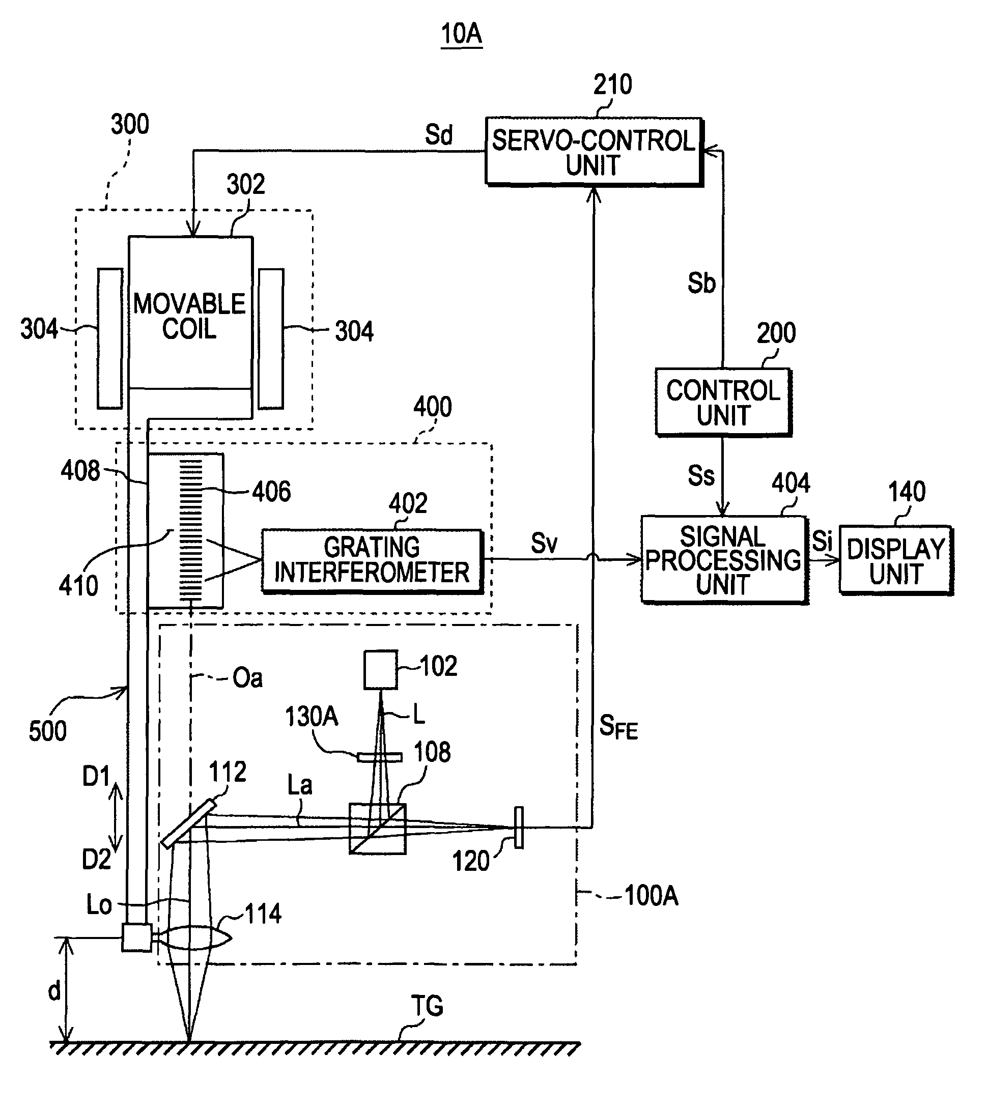
[0032]FIG. 1 is a block diagram of a displacement detecting device 100A according to the first embodiment of the present invention. As shown in FIG. 1, the displacement detecting device 100A includes a non-contact sensor 100A, a control unit 200, a servo-control unit 210, an actuator 300, a displacement-amount measuring unit 400, a signal processing unit 404, and a display unit 140. For the sake of convenience, the configuration of the non-contact sensor 100A is shown in a simplified form in FIG. 1.

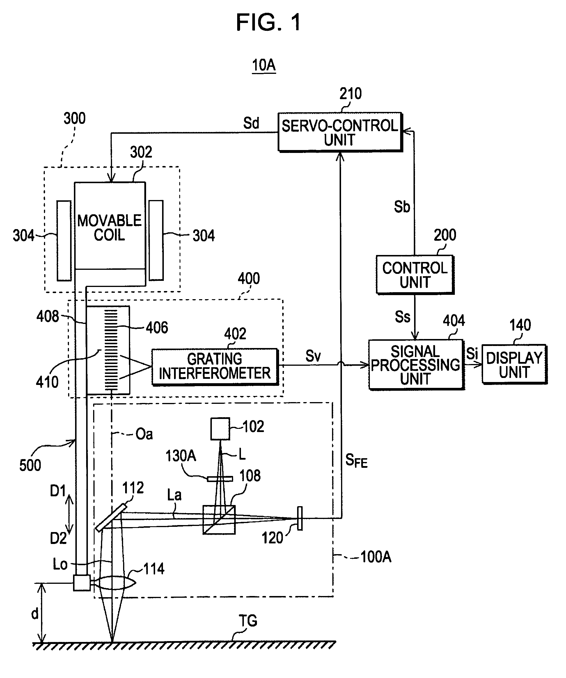
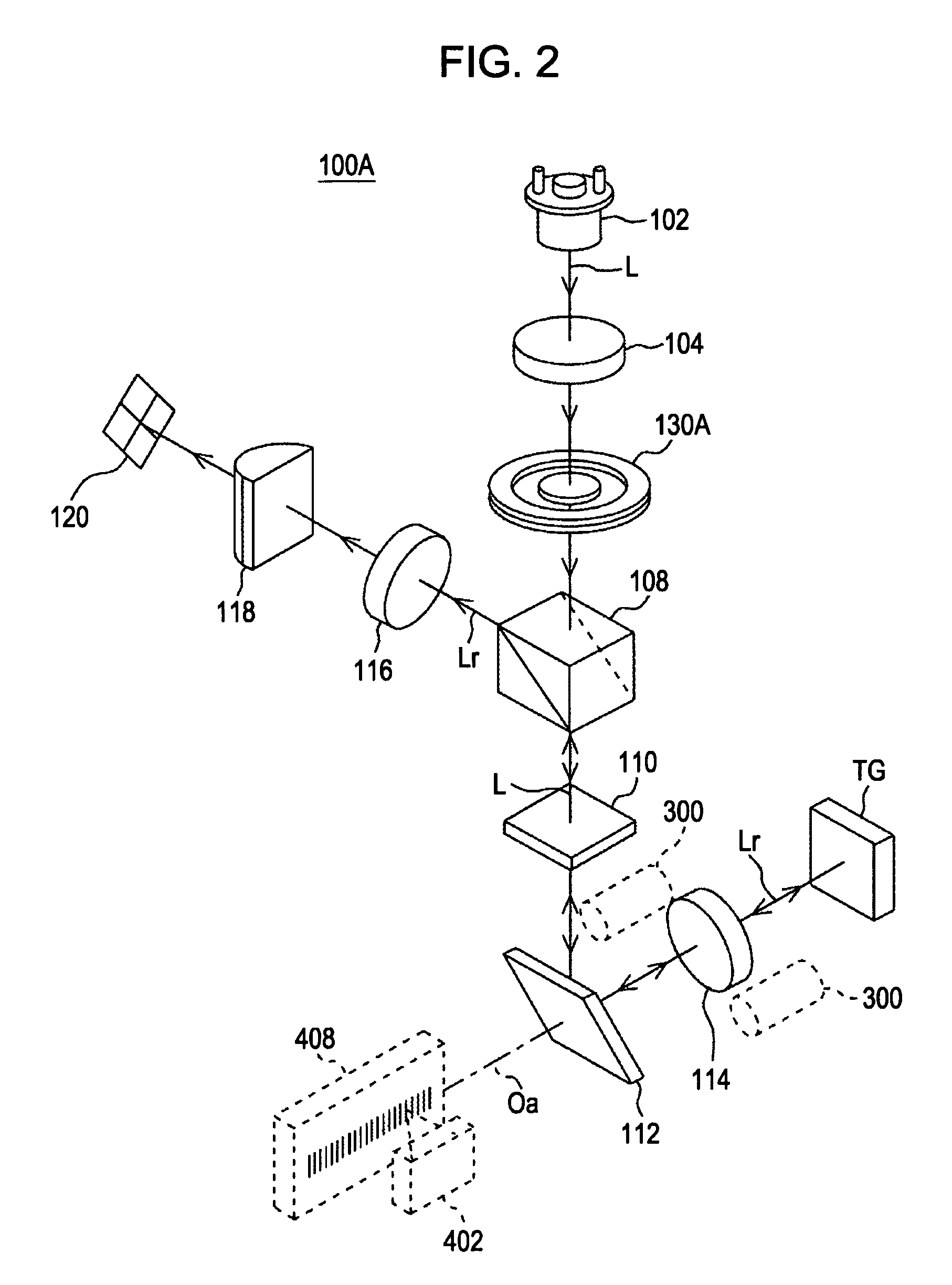
[0033]FIG. 2 is a perspective view showing the configuration of the non-contact sensor 100A. As shown in FIG. 2, the non-contact sensor 100A includes a light source 102, a collimator lens 104, a light adjustment member 130A, a polarizing beam splitter 108, a quarter-wave plate 110, a mirror 112, a first objective lens 114, a second objective lens 116, an astigmatism generating lens 118...

second embodiment

[0066]A second embodiment of the present invention is equipped with a light adjustment member 130B having a configuration different from that of the aforementioned light adjustment member 130A. FIG. 8A is a plan view showing the configuration of the light adjustment member 130B. FIG. 8B is a cross-sectional view taken along line VIIIB-VIIIB in FIG. 8A. FIG. 8C illustrates a functional example of the light adjustment member 130B.

[0067]As shown in FIGS. 8A and 8B, the light adjustment member 130B is formed of a flat plate having a circular shape in plan view and composed of, for example, a metallic material or a glass material. The light adjustment member 130B has a main light-adjustment-member body 138b, a light blocking section 136b that blocks a paraxial ray of the output light L, and an aperture section 132b that transmits the output light L toward the measurement surface TG.

[0068]The light blocking section 136b is provided in the middle of the main light-adjustment-member body 13...

third embodiment

[0071]A third embodiment of the present invention will be described below with reference to the drawings. A light adjustment member 130C in this embodiment differs from those in the first and second embodiments in that it functions as a member that prevents entry of diffracted light from an object to be measured. Components that are similar to those in the displacement detecting device 100A and the non-contact sensor 100A described in the first embodiment are given the same reference numerals, and the detailed description thereof will be omitted here.

[0072]FIG. 9 is a perspective view showing the configuration of a non-contact sensor 100B. As shown in FIG. 9, the non-contact sensor 100B includes the light source 102, the collimator lens 104, the light adjustment member 130C, the polarizing beam splitter 108, the quarter-wave plate 110, the mirror 112, the first objective lens 114, the second objective lens 116, the astigmatism generating lens 118, and the light receiving element 120...


PUM

PropertyMeasurementUnit
diameteraaaaaaaaaa
focal lengthaaaaaaaaaa
incident angleaaaaaaaaaa

Abstract

A displacement detecting device includes a non-contact sensor having a light source, an objective lens focusing output light from the light source onto a measurement surface, and a light receiving element detecting displacement information based on a focal length of the objective lens by using reflected light from the measurement surface; a control unit adjusting the focal length based on the displacement information; a displacement-amount measuring unit having a linear scale attached to the objective lens with a link member therebetween and measuring an amount of displacement of the linear scale when the focal length is adjusted. A light adjustment member is disposed between the light source and the objective lens or between the objective lens and the light receiving element and has an aperture section transmitting the output and / or reflected light therethrough and a light blocking section that blocks a specific light component of the output and / or reflected light.

Description

BACKGROUND OF THE INVENTION[0001]1. Field of the Invention[0002]The present invention relates to displacement detecting devices that detect relative displacement between an objective lens and a surface to be measured by using an optical astigmatic method. More specifically, the present invention relates to a displacement detecting device having a light adjustment member disposed between a light source and an objective lens so as to adjust the resolution of output light focused on a surface to be measured or having a light adjustment member disposed between an objective lens and a light receiving element for regulating an incident angle of reflected light reflected by the surface to be measured so as to accurately measure the surface roughness of the surface to be measured.[0003]2. Description of the Related Art[0004]In the related art, displacement detecting devices have been widely used for measuring the displacement and the shape of a surface to be measured (which will be referred...

Claims


Application Information

Patent Timeline
Patent Type & Authority Patents(United States)
IPC IPC(8): G01N21/86H01J3/14
CPCG01B11/00G01B11/026G01B11/303G01D5/38
Inventor TAMIYA, HIDEAKITANIGUCHI, KAYOKO
Owner DMG MORI CO LTD
Why Eureka
Try Eureka