X-ray detector

a detector and x-ray technology, applied in the field of x-ray detectors, can solve the problems of image errors, unwanted artifacts in the implementation of such corrections, and inability to achieve the effect of simple and cost-effectiv

Inactive Publication Date: 2007-07-03
SIEMENS HEALTHCARE GMBH
View PDF5 Cites 0 Cited by
  • Summary
  • Abstract
  • Description
  • Claims
  • Application Information

AI Technical Summary

Benefits of technology

[0007]An object of the present invention is to provide an x-ray detector wherein the disadvantages according to the prior art are avoided. In particular, such an x-ray detector should enable the measurement of a radiation dose rate in a simple and cost-effective manner.
[0008]This object is achieved in accordance with the invention by a radiation detector of the type initially described, and having a second photodiode on a radiation-incident surface of the luminophore, the second photodiode having a light-sensitive (active) surface facing the first photodiode. The invention makes use of the fact that the light produced in the luminophore does not exit at only one of the exit surfaces opposite the incident surface, but also exits from the incident surface itself. By detection of the light exiting from the incident surface, a radiation dose rate can be determined. The dose rate thus can be measured in a simple manner. Given a suitable design of the further photodiodes, no structures whatsoever are imaged. The formation of image errors and artifacts is prevented. The provision of a separate apparatus to measure the dose rate is not necessary. The proposed x-ray detector can be produced relatively simply and cost-effectively.
[0012]According to a further embodiment, a layer that is partially transparent to light can be provided between the luminophore and the further photodiode. This can be what is known as a semi-transparent layer that reflects a portion of the incident light. The light yield on the exit surface thus can be increased by the use of such a layer.
[0013]According to a further embodiment, each photodiode has a switch. The photodiodes appropriately form photodiode array. Each further photodiode can likewise include a further switch. The further photodiodes can form a further photodiode array. The provision of a switch for each photodiode and each further photodiode enables a sequential line-by-line readout of the charges stored by the photodiodes and the further photodiodes. By reading out the photodiodes, spatially resolved information about incident x-rays can be acquired. The readout of the further photodiodes enables the determination of a radiation dose rate.
[0014]The luminophore can be fashioned as a layer overlaying the photodiode array. This simplifies the production of the inventive x-ray detector and reduces the price thereof.
[0015]According to a further embodiment, a detection surface of the further photodiode is larger than a detection surface of the photodiode. The number of the photodiodes can appropriately be a (preferably even) multiple of the number of the further photodiodes. A detection surface of one of the further photodiodes appropriately covers the detection surfaces of a number of the photodiodes. To determine a radiation dose rate, a precise, spatially resolved measurement of incident x-ray radiation is not necessary. A rough spatially resolved measurement over the total detection surface formed by the photodiode array is sufficient.

Problems solved by technology

The structures formed by such detectors are disadvantageously imaged on the x-ray detector and undesirably adulterate the image information.
In specific cases, however, unwanted artifacts can occur in the implementation of such a correction.
Conventional apparatuses to measure the dose are elaborate and, among other things, cause image errors.

Method used


Image

  • X-ray detector
  • X-ray detector
  • X-ray detector

Examples


first embodiment

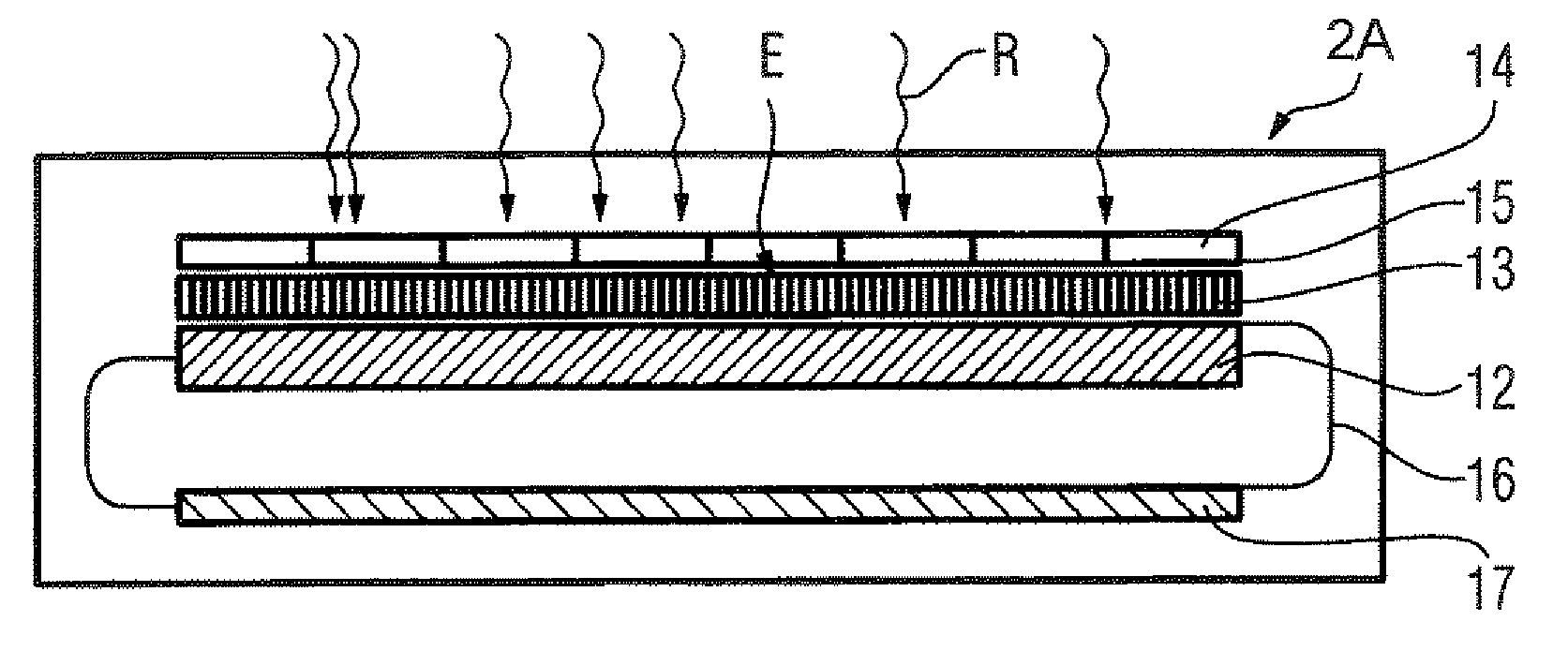
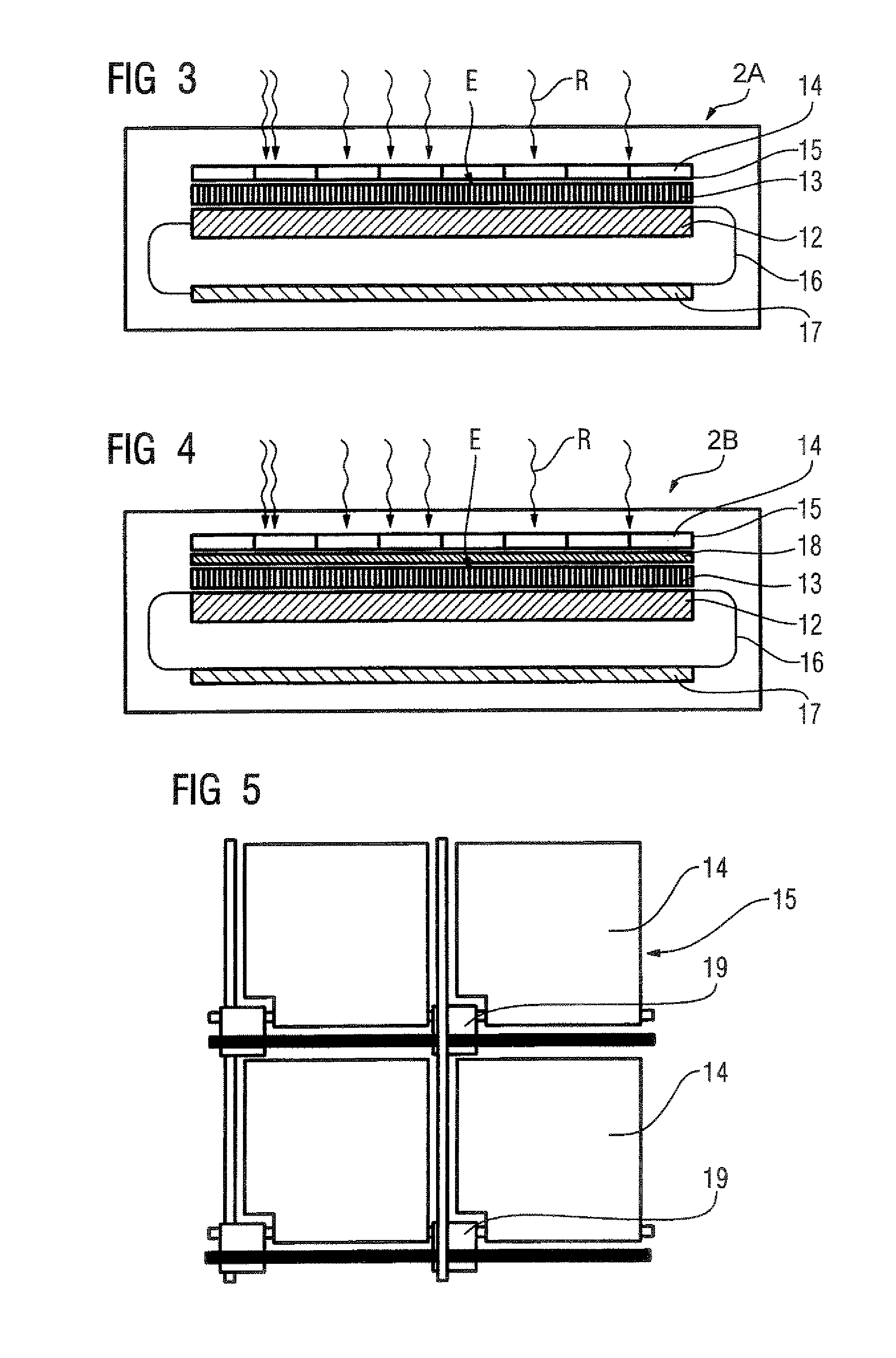
[0024]FIG. 3 shows a schematic cross-section view of an inventive x-ray detector 2A. The luminophore layer 13 is located on the photodiode array 12 produced, for example, from amorphous silicon. A further photodiode array 15 formed from a number of further photodiodes 14 is located on the incident surface E of the luminophore layer 13. The photodiode array 12 is connected by means of a connection line 16 with an electronic evaluation circuit 17. The light-sensitive surface of each further photodiode 14 faces the photodiode array 12.

second embodiment

[0025]In the inventive x-ray detector 2B shown in FIG. 4, a layer 18 that is semi-transparent for light is disposed on the incident surface E of the luminophore layer 13. The further photodiode array 15 is located on the semi-transparent layer 18.

[0026]FIG. 5 shows a plan view of a section of the further photodiode array 15. A switch 19 is associated with each of the further photodiodes 14. It is thereby possible to read out line-by-line the charges measured with the further photodiodes 14. The charges read out can be integrated with a suitable integration device. The radiation dose rate can be determined from the integrated measurement values with spatial resolution.

[0027]FIG. 6 shows a plan view of the further photodiode array 15. To determine a radiation dose rate, it is, for example, possible to select a predetermined region B that is formed from a number of the further photodiodes 14 for use in determining the dose rate.

[0028]The further photodiodes 14 are appropriately produce...


PUM


Abstract

An x-ray detector has a number of detector elements, each formed from a first photodiode and a luminophore applied thereon. To measure the dose rate, a second photodiode is provided on an incident surface of the luminophore facing the first photodiode.

Description

BACKGROUND OF THE INVENTION[0001]1. Field of the Invention[0002]The invention concerns an x-ray detector of the type having a number of detector elements, each formed by a photodiode and a luminophore.[0003]2. Description of the Prior Art[0004]An x-ray detector of the above general type is known from “Digital Radiography with a Large-Area, Amorphous-Silicon, Flat-Panel X-Ray Detector System” by Spahn M. et al., Investigative Radiology 2000; Vol. 35, pages 260–266. In this known x-ray detector, a photodiode matrix (formed, for example, from amorphous silicon (a-Si)) is overlaid by a luminophore layer (formed, for example, from cesium iodide (Csl)). X-ray radiation radiated onto the luminophore layer is transduced into light in the luminophore layer. The light is detected with spatial resolution by the photodiode matrix and the resulting electrical signals are further processed by means of a downstream image-processing device.[0005]In particular in radiography, it is sought for medica...

Claims


Application Information

Patent Timeline
Patent Type & Authority Patents(United States)
IPC IPC(8): G01T1/20G01T1/29
CPCG01T1/2018
Inventor SPAHN, MARTIN
Owner SIEMENS HEALTHCARE GMBH
Why Eureka
Try Eureka