Wedged Profile Plate
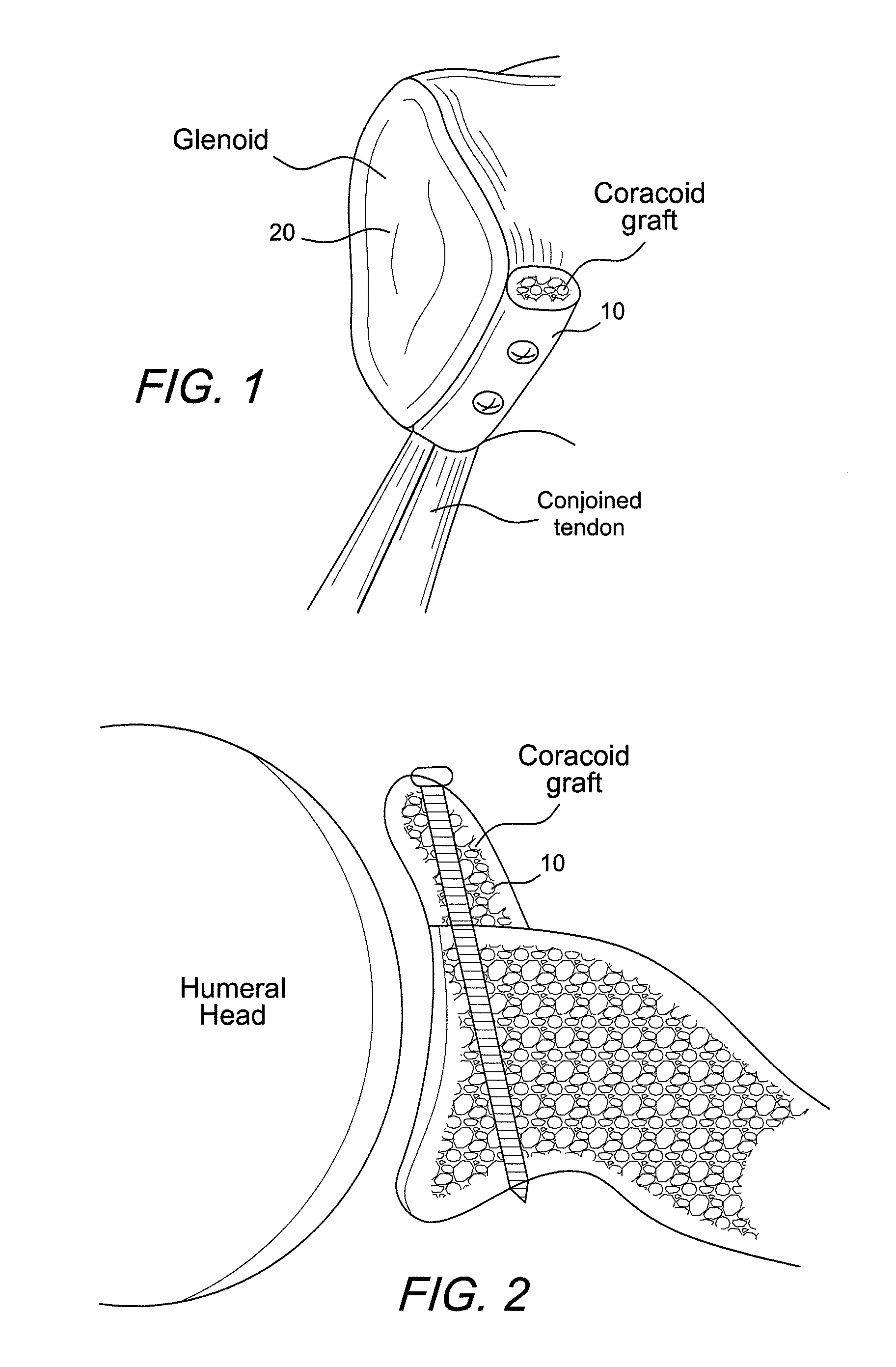
a profile plate and profile technology, applied in the field of new bone plates, can solve the problems of increasing the possibility of intra-articular protrusion of screws, preventing the perfect orientation of drills and screwdrivers, and always a danger of coracoid process breakage,
- Summary
- Abstract
- Description
- Claims
- Application Information
AI Technical Summary
Benefits of technology
Problems solved by technology
Method used
Image
Examples
first embodiment
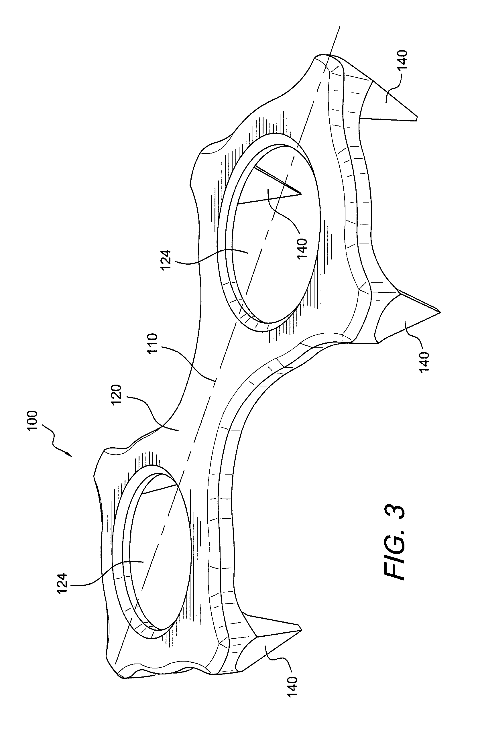
[0020]Bone plate 100 of the present invention (shown in FIGS. 3-5) includes a rigid plate body 120 having an elongated “FIG. 8” configuration, as shown in FIG. 3, for example. As illustrated in FIG. 5a, and according to an exemplary embodiment of the invention, rigid body 120 has a length “L” of about 15 to 20 mm, more preferably of about 18 mm, and a width “W” of about 5 to about 10 mm, more preferably of about 6.5 mm.
[0021]Bone plate 100 is also provided with a plurality of small projecting teeth, protuberances or spikes 140. Projecting teeth or spikes 140 are designed to allow the plate 100 to stay in the right position (once the surgeon has pressed the plate with his / her fingers, or using a specific instrument, on the bone block) before the fixation holes are drilled and before the fixation devices (for example, screws) are secured. The exemplary embodiment illustrated in FIGS. 3-5 shows bone plate 100 provided with six spikes 140, two of the spikes being positioned on the longi...
second embodiment
[0024]Bone plate 200 of the present invention (shown in FIGS. 6-8) includes a rigid plate body 220 having an oval shape and provided with a plurality of small projecting teeth, protuberances or spikes 240 (two shown in FIGS. 6-8). Spikes 240 are similar to spikes 140 of plate 100 in that spikes 240 are also provided with a truncated, pyramidal shape, each spike terminating in tip 250 having a length “l” (FIG. 8b) of about 0.1 to 0.2 mm. The height “H” of each spike is of about 3 mm with the bone plate (FIG. 8b) or of about 2.5 mm (without the bone plate).
[0025]Body plate 220 is also provided with two openings 224 (that may be threaded and / or countersunk) configured to receive fixation devices (such as, for example, two fixation devices used for the Latarjet procedure). Projecting teeth or spikes 240 are designed to allow the plate 200 to stay in the right position (once the surgeon has pressed the plate with his / her fingers, or using a specific instrument, on the bone block) before ...
third embodiment
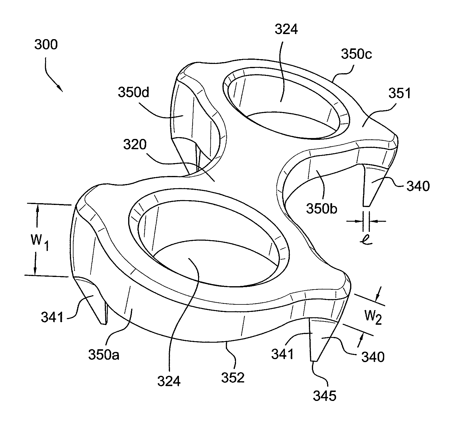
[0027]Bone plate 300 of the present invention (shown in FIG. 9) has a wedged design (as opposed to the parallel design of FIG. 6, for example). The special profile of the plate 300 enables orthograde placement of the fixation device (for example, a screw) even in the case of angled bone surfaces.
[0028]As shown in FIG. 9, bone plate 300 is provided with a rigid body 320 and four spikes 340 provided symmetrically relative to a longitudinal axis 310 of body 320. Spikes 340 are rigid and, according to an exemplary embodiment only, are provided integral with the body 320. Spikes 340 have a truncated, pyramidal shape with a plurality of sides or faces 341 that converge to tip 345 (line 345) of each spike 340. In an exemplary embodiment only, at least one of the spikes has four lateral faces 341 that converge to tip 345. In a preferred embodiment, all spikes have four lateral faces 341 that converge to tip 345. Tip 345 is preferably a thin line with a length “l” of about 0.1 to 0.2 mm. The...
PUM
 Abstract
Description
Claims
Application Information
 - R&D
- Intellectual Property
- Life Sciences
- Materials
- Tech Scout
- Unparalleled Data Quality
- Higher Quality Content
- 60% Fewer Hallucinations
Browse by: Latest US Patents, China's latest patents, Technical Efficacy Thesaurus, Application Domain, Technology Topic, Popular Technical Reports.
© 2025 PatSnap. All rights reserved.Legal|Privacy policy|Modern Slavery Act Transparency Statement|Sitemap|About US| Contact US: help@patsnap.com


