Coupling the viewing direction of a blood vessel's CPR view with the viewing angle on the 3D tubular structure's rendered voxel volume and/or with the C-arm geometry of a 3D rotational angiography device's C-arm system

a technology of c-arm and cpr, which is applied in the direction of 3d-image rendering, instruments, computing, etc., can solve the problems of patient exposure to potentially harmful contrast agents and patient and staff exposure to x-ray radiation dose, and achieve the effect of facilitating accurate measurements of the vessel

Active Publication Date: 2014-05-20
KONINK PHILIPS ELECTRONICS NV
View PDF8 Cites 46 Cited by
  • Summary
  • Abstract
  • Description
  • Claims
  • Application Information

AI Technical Summary

Benefits of technology

[0012]Curved planar reformat images are commonly used when reviewing arteries in CT reconstructions, e.g. in the diagnosis of coronary artery disease. One advantage consists in the fact that a curved planar reformat image is able to display blood vessels without any spatial foreshortening and to display the surrounding tissue regions in the interior of a patient's body to be examined. The absence of spatial foreshortening facilitates accurate measurements on the vessels. If a narrowing of the vessel (e.g. a lesion or a stenosis, etc.) is found on the CT, an intervention is performed in a cardiovascular X-ray cathlab. Lesions are often eccentric, which means that the minimum cross-section of a lesion is only visible in a specific orientation of a curved reformatted view. At the start of cardiovascular interventions, X-ray angiographic images were acquired in several views so as to confirm the diagnosis made on a computed tomogram. Depending on the respective patient's anatomy, a substantial number of angiographies are needed to find a view on the anatomy that shows the minimum cross-sectional area of the lesion. This means patient exposure to potentially harmful contrast agent and both patient and staff exposure to X-ray radiation dose.
[0013]It may thus be an object of the present invention to integrate pre-procedural diagnostic curved reformat views in the minimally invasive treatment of ulcerated stenoses, aneurysms, lesions or other vascular pathologies so as to reduce the number of unnecessary angiographies which are needed to find a specific viewing direction on pathological objects to be visualized, said view direction being given by the viewing angle on a segmented or raw representation of the 3D tubular structure's rendered voxel volume to be visualized or by the C-arm roll, pitch and yaw angle of a 3D rotational angiography device's C-arm system, respectively, and hence to reduce the patient and clinical staff exposure to X-ray radiation dose and provide for an improved diagnostic workflow.
[0019]According to a fourth mode of said method, the C-arm geometry of a 3D rotational angiography device's C-arm system given by the roll, pitch and yaw angle of the C-arm is set depending on the viewing direction of the curved planar reformat view. This enables a clinician to let the X-ray image correspond as closely as possible to a view that has been planned by using said curved planar reformat view. It allows a comparison of the acquired angiographic X-ray data with the pre-procedural CT / MR data in the same orientation.
[0021]A sixth mode of said method is directed to a variant whereupon a fused visualization of the 3D tubular structure's curved planar reformat view and a 2D projection image (such as e.g. an X-ray image or a rendered 2D view) showing a two-dimensional projection of this structure may be rendered and displayed. This is different from conventional image fusing techniques as known from the prior art, whereupon a blood vessel's 3D tubular structure is projected into the coordinate space of the 2D projection image. According to said sixth mode, the 2D projection image is re-projected into the coordinate space of the curved planar reformat view by being submitted to a spatial deformation algorithm that yields transformed image data matching with the spatial course of the 3D tubular structure in the curved planar reformat view's coordinate space. This leads to a fused image representation that is essentially free of spatial foreshortening and enables direct measurements which do not need to be calibrated.

Problems solved by technology

Lesions are often eccentric, which means that the minimum cross-section of a lesion is only visible in a specific orientation of a curved reformatted view.
This means patient exposure to potentially harmful contrast agent and both patient and staff exposure to X-ray radiation dose.

Method used


Image

  • Coupling the viewing direction of a blood vessel's CPR view with the viewing angle on the 3D tubular structure's rendered voxel volume and/or with the C-arm geometry of a 3D rotational angiography device's C-arm system
  • Coupling the viewing direction of a blood vessel's CPR view with the viewing angle on the 3D tubular structure's rendered voxel volume and/or with the C-arm geometry of a 3D rotational angiography device's C-arm system
  • Coupling the viewing direction of a blood vessel's CPR view with the viewing angle on the 3D tubular structure's rendered voxel volume and/or with the C-arm geometry of a 3D rotational angiography device's C-arm system

Examples


Embodiment Construction

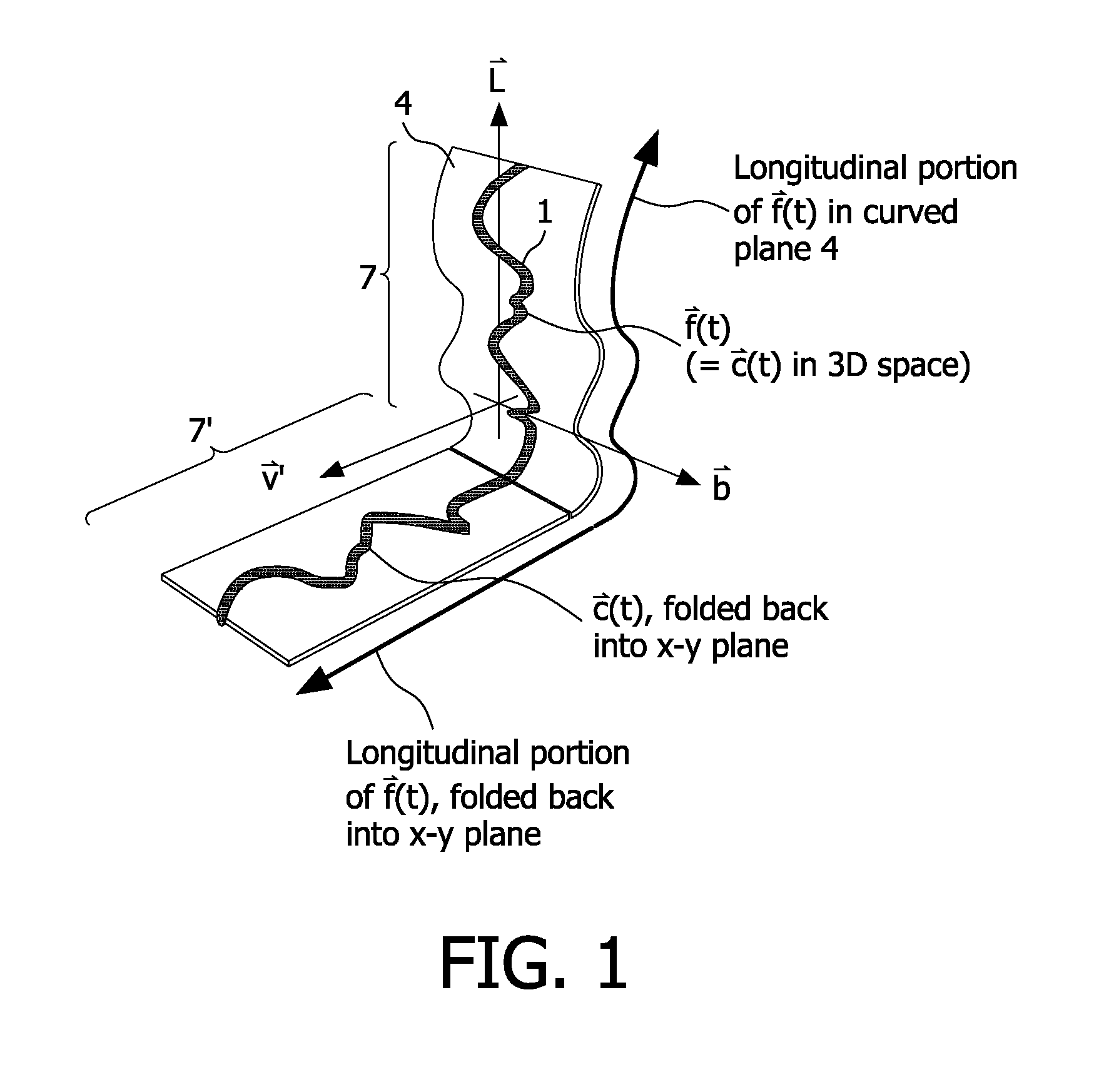
[0035]In the following, the CPR-based visualization method according to an exemplary embodiment of the present invention will be explained in more detail with respect to special refinements and referring to the accompanying drawings. Thereby, a blood vessel's 3D tubular structure 1 that has been segmented from an acquired CT or MR image by means of a segmentation algorithm, said 3D tubular structure being sufficiently described by a curvilinear central axis, shall be assumed as being an anatomical object to be graphically visualized.

[0036]When defining the path of said blood vessel's 3D tubular structure's central axis by {right arrow over (x)}={right arrow over (f)}(t), whereby {right arrow over (x)} denotes the Cartesian position vector of a 3D position P(x, y, z) in a three-dimensional Cartesian coordinate system of an Euclidian vector space V=3 and t is a real-valued scalar parameter ranging from 0 to 1, the normalized longitudinal vector {right arrow over (l)} of the central ax...


PUM


Abstract

The present invention describes a method for rendering and displaying a curved planar reformat (CPR) view (7′) of a blood vessel's 3D tubular structure (1), wherein the viewing direction of the curved planar reformat view (7′) is coupled to the viewing angle on a segmented or raw representation of the 3D tubular structure's rendered voxel volume to be visualized or, alternatively, to the C-arm geometry of a 3D rotational angiography device's C-arm system (6). The proposed method thus enables measurements on the X-ray image which do not suffer from spatial foreshortening and do not need to be calibrated. Thereby, said coupling can be performed bidirectional. According to a first aspect of the proposed method, this means that the viewing direction of the aforementioned curved planar reformat view (7′) follows the viewing angle on a segmented or raw representation of the 3D tubular structure's rendered voxel volume to be visualized, or vice versa. According to another aspect of the proposed method, this means that the viewing direction of the curved planar reformat view (7′) is set depending on the C-arm geometry given by the roll (θx), pitch (θy) and yaw angle (θz) of a 3D rotational angiography device's C-arm system (6), or vice versa.

Description

FIELD OF THE INVENTION[0001]The present invention describes a method for rendering and displaying a curved planar reformat (CPR) view of a blood vessel's 3D tubular structure, wherein the viewing direction of the curved planar reformat view is coupled to the viewing angle on a segmented or raw representation of the 3D tubular structure's rendered voxel volume to be visualized and / or to the C-arm geometry of a 3D rotational angiography device's C-arm system. The proposed method enables measurements on the X-ray image which do not suffer from spatial foreshortening and do not need to be calibrated.BACKGROUND OF THE INVENTION[0002]Non-invasive imaging of the vascular system with the aid of computed tomography (CT) and magnetic resonance imaging (MRI) has become a well-established alternative to invasive intra-arterial angiography. Both CT and MRI provide high-resolution volumetric data sets that can be used for visualizing anatomical objects (internal organs, bones and joints, blood ve...

Claims


Application Information

Patent Timeline
Patent Type & Authority Patents(United States)
IPC IPC(8): G06T15/08G06T19/00G06T15/00
CPCG06T19/00G06T2215/06G06T2210/41G06T15/08
Inventor RUIJTERS, DANIEL SIMON ANNABAKKER, NICOLAAS HYLKEHOMAN, ROBERT JOHANNES FREDERIK
Owner KONINK PHILIPS ELECTRONICS NV
Why Eureka
Try Eureka