Dual clutch and method for controlling the same

a technology of clutches and clutch springs, applied in the direction of clutches, clutches, mechanical actuated clutches, etc., can solve the problems of possible interference between the lever springs, and achieve the effect of increasing the actuating path and saving the axial installation spa

Inactive Publication Date: 2014-05-27
SCHAEFFLER TECH AG & CO KG
View PDF5 Cites 0 Cited by
  • Summary
  • Abstract
  • Description
  • Claims
  • Application Information

AI Technical Summary

Benefits of technology

[0009]According to the invention, the two friction clutches are designed in such a way that no intersecting, axially interfering movement of the lever springs occurs during an overlapping shift. This can be achieved, for example, by redesigning the shift patterns of the friction clutches. For example, an advantageous illustrative embodiment can provide a dual clutch in which a first of the friction clutches is designed as a pull-shut friction clutch and a second of the friction clutches is designed as a press-open friction clutch, or in which a first of the friction clutches is designed as a press-shut friction clutch and a second of the friction clutches is designed as a pull-open friction clutch. If, for example, in respect of the counterpressure plate, the first friction clutch faces the internal combustion engine and is actuated by means of a tie rod which passes through or overlaps the counterpressure plate and is acted upon by the lever spring, the first friction clutch is closed, e.g. pulled shut, and the second friction clutch is pressed open when the lever springs are acted upon by the corresponding actuating systems in the direction of the internal combustion engine. During an overlapping shift, the two lever springs are moved substantially in synchronism and can therefore be arranged at a comparatively small axial distance from one another, hence saving axial installation space.
[0010]To increase the actuating path, especially that of the press-open friction clutch, the contact plate can be chamfered radially on the inside in the actuating direction of the lever spring. By means of a conical, radially inward taper of the contact plate or by means of recesses introduced into the latter for the lever elements of the lever spring, the lever spring can be moved by an increased actuating path in the direction of the internal combustion engine, thus enabling the other lever spring to be moved axially closer thereto.

Problems solved by technology

At most, the possibility of interference between the lever springs would arise when both friction clutches were closed.
However, since this state is critical for safety in a dual clutch transmission, this state is not set by means of the automatically operated actuating systems.

Method used


Image

  • Dual clutch and method for controlling the same
  • Dual clutch and method for controlling the same
  • Dual clutch and method for controlling the same

Examples


Embodiment Construction

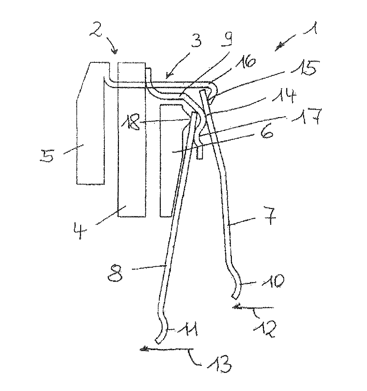
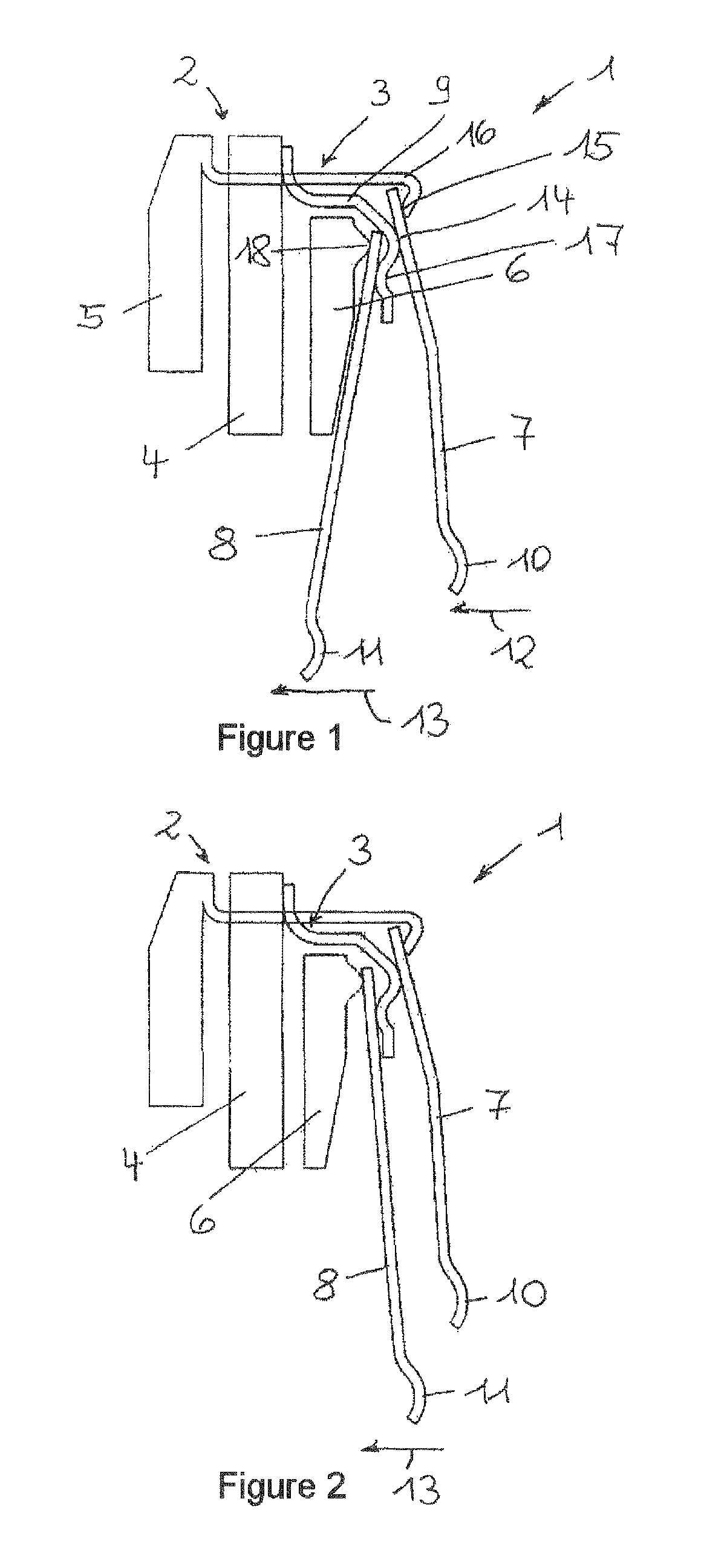
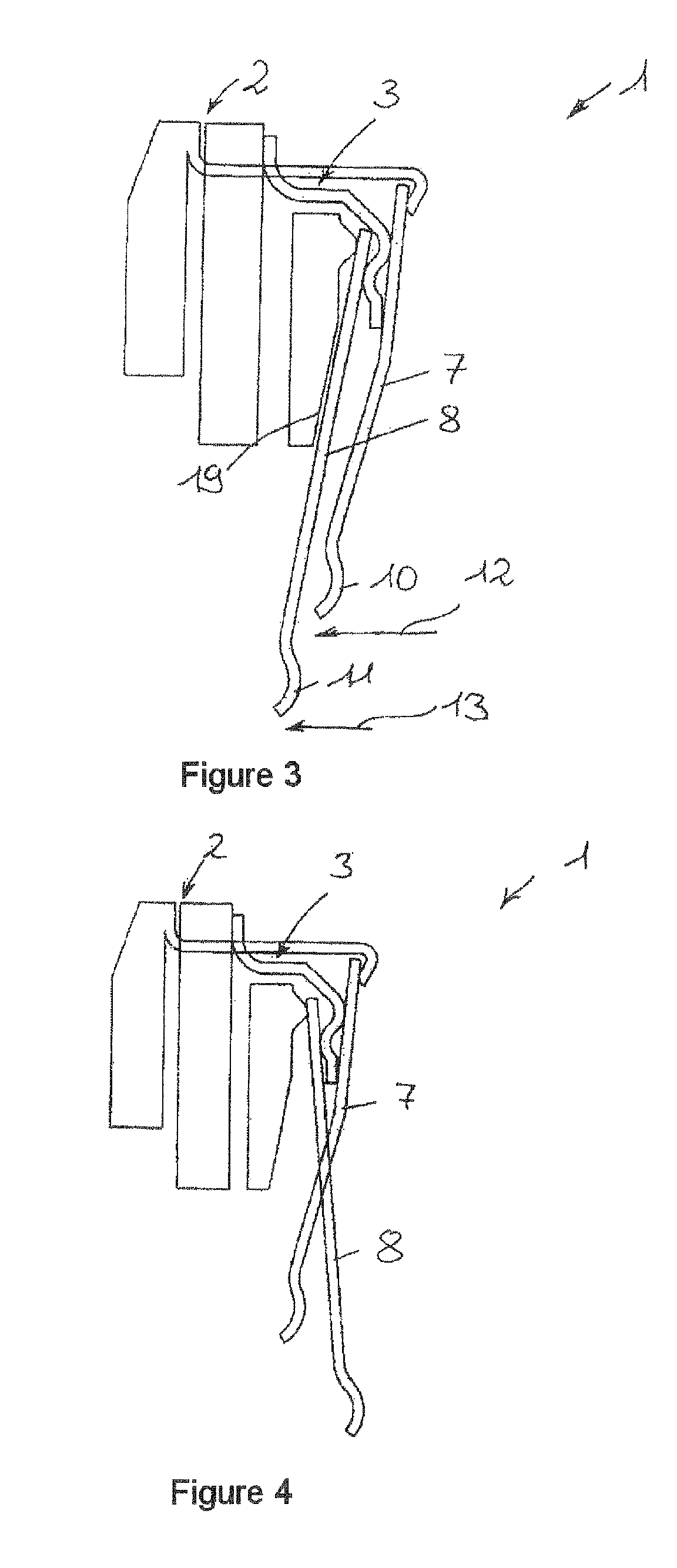
[0019]FIG. 1 shows a schematic partial section through the dual clutch 1, which is rotationally symmetrical about an axis of rotation, with the friction clutches 2, 3. The two friction clutches 2, 3 have a common counterpressure plate 4, which is firmly connected to a crankshaft of an internal combustion engine in a manner not shown, and respective contact plates 5, 6, which can be moved axially to a limited extent relative to said counterpressure plate and are connected for conjoint rotation. Friction linings (not shown) of respective clutch disks are provided axially between the contact plates 5, 6 and the counterpressure plate 4 in a manner which allows them to be clamped axially. The clutches can be designed as single-disk clutches, having one clutch disk with a pair of friction surfaces, or as multi-disk clutches having a disk pack with more than two friction surfaces. To enlarge the friction surface area of the clutches, it is, however, also possible for each of the clutch dis...


PUM


Abstract

A dual clutch and a method for controlling the same in a drive train of a motor vehicle which has two friction clutches that transmit a torque from an internal combustion engine to respective transmission input shafts of a dual clutch transmission and which have a common counterpressure plate firmly connected to a crankshaft of the internal combustion engine and two contact plates that are fixed in terms of rotation relative to the counterpressure plate and can be moved axially by respective lever springs supported on a housing part firmly connected to the counterpressure plate. To limit the axial installation space for the dual clutch, the lever springs for actuating the friction clutches are actuated radially on the inside in the same direction by respective actuating systems in the case of a change from one friction clutch to the other of a torque to be transmitted via the friction clutches.

Description

CROSS-REFERENCE TO RELATED APPLICATION[0001]This application claims the priority of DE 10 2010 022 919.9 filed Jun. 7, 2010 and DE 10 2010 026 837.2 filed Jul. 12, 2010, which are both incorporated by reference herein.FIELD OF THE INVENTION[0002]The invention relates to a dual clutch and to a method for controlling a dual clutch in a drive train of a motor vehicle having two friction clutches.BACKGROUND OF THE INVENTION[0003]A dual clutch of the type in question in the form of a clutch unit with two friction clutches is known from WO 2008 / 058508 A1. Here, a counterpressure plate is firmly connected for conjoint rotation to a crankshaft of an internal combustion engine by means of housing components. On both sides, the counterpressure plate forms friction surfaces for contact with friction linings of respective clutch disks connected for co-rotation with a transmission input shaft of a dual clutch transmission. Provided at an axial distance from said friction surfaces, on both sides,...

Claims


Application Information

Patent Timeline
Patent Type & Authority Patents(United States)
IPC IPC(8): F16D21/06F16D13/58
CPCF16D2021/0607F16D21/06F16D2021/0684
Inventor HOPPE, MARCUS
Owner SCHAEFFLER TECH AG & CO KG
Why Eureka
Try Eureka