
Dual-chambered shot glass

a shot glass and dual-chamber technology, applied in the field of shot glass, can solve the problems of not solving the problem, not having a movable divider between the chambers of the beverage container, and not having a hinged flap divider in the prior art device,

Inactive Publication Date: 2014-05-27
MICHAELS PAUL
View PDF8 Cites 9 Cited by
  • Summary
  • Abstract
  • Description
  • Claims
  • Application Information

AI Technical Summary

Benefits of technology

[0014]The shot glass is an easy to use beverage container that prevents two beverages from mingling prior to ingestion by a user. Because the two drinks are served in the same glass, bartenders will not have to dirty two glasses to serve the drink. This makes the invention more time and cost efficient for bar staff. Additionally, the size of the chaser is equivalent tot hat of the shot of liquor and can be priced accordingly by a bar manager. Patrons will appreciate saving money when they do not have to purchase full-sized beverages just to enjoy a small sip with a shot of hard liquor. In this way, the present invention provides a convenient and cost effective means for serving liquor and chasers to bar patrons.
[0018]Yet another object of the present invention is to provide a means for bar patrons to enjoy a shot of hard liquor and a chaser beverage at the same time.
[0019]A further object of the present invention is to provide a means for bar patrons to enjoy a shot of hard liquor and a chaser without having to purchase a full size chaser beverage.

Problems solved by technology

The prior art discloses several dual-chambered devices but none of them have a movable divider between chambers of the beverage container.
A similar problem exists with dual-chambered beverage containers that comprise a chamber within a chamber.
This design improves upon the vertical bi-chambered glass of Moran, but does not solve the problem of providing a user with one beverage after the other.
None of the prior art devices includes two stacked chambers, nor do they disclose a hinged flap divider.

Method used


Image

  • Dual-chambered shot glass
  • Dual-chambered shot glass
  • Dual-chambered shot glass

Examples


Embodiment Construction

[0027]Reference is made herein to the attached drawings. Like reference numerals are used throughout the drawings to depict like or similar elements of the dual-chambered beverage container. For the purposes of presenting a brief and clear description of the present invention, the preferred embodiment will be discussed as used for providing a user with a means for drinking a shot of hard liquor at the same time as a chaser beverage. The figures are intended for representative purposes only and should not be considered to be limiting in any respect.

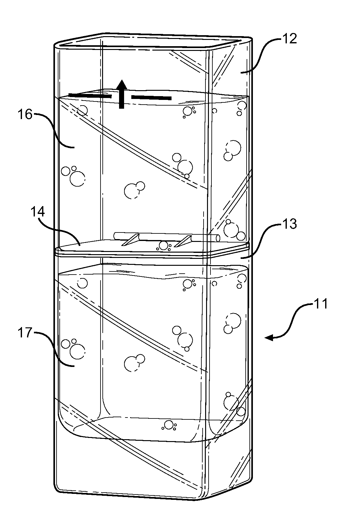
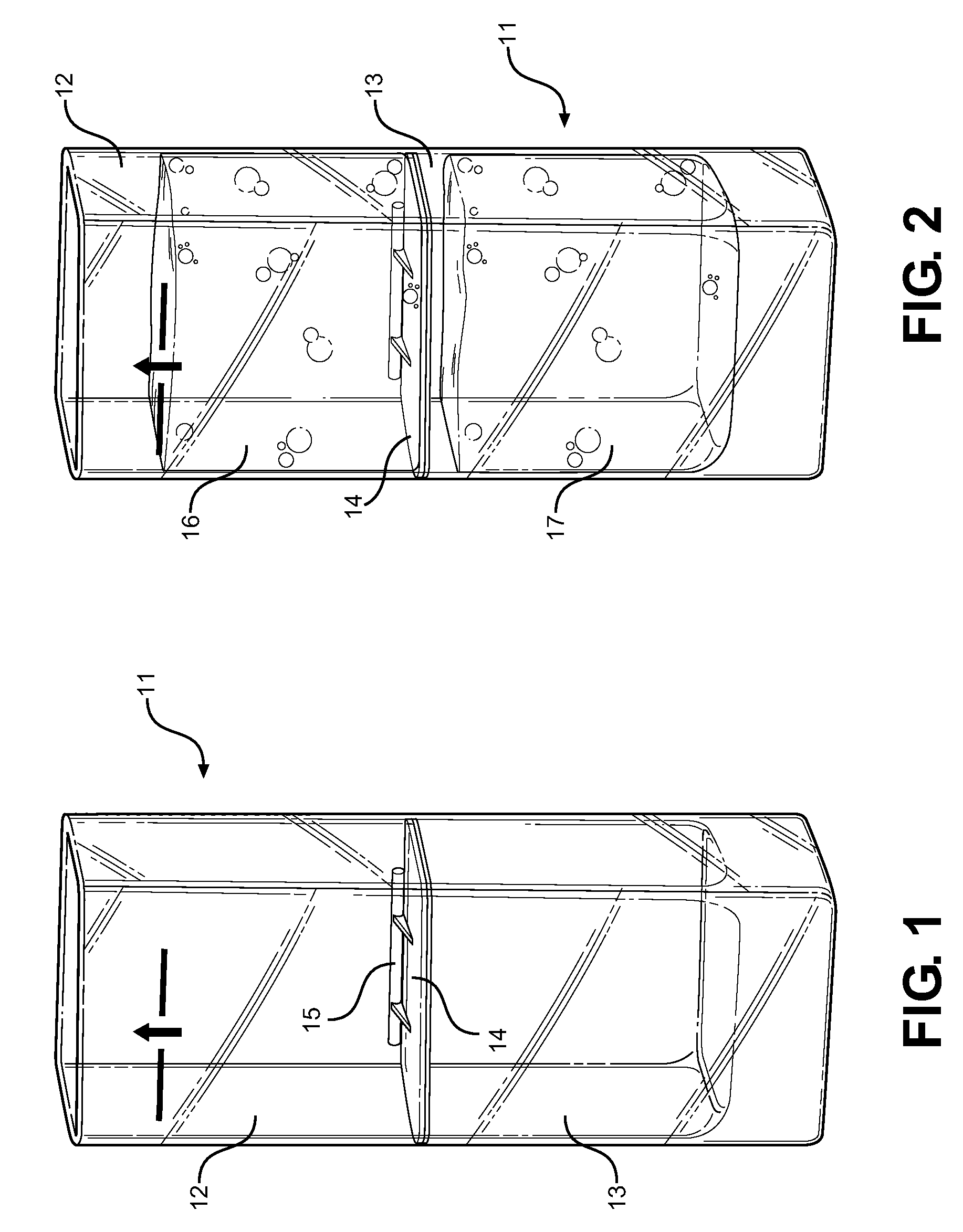
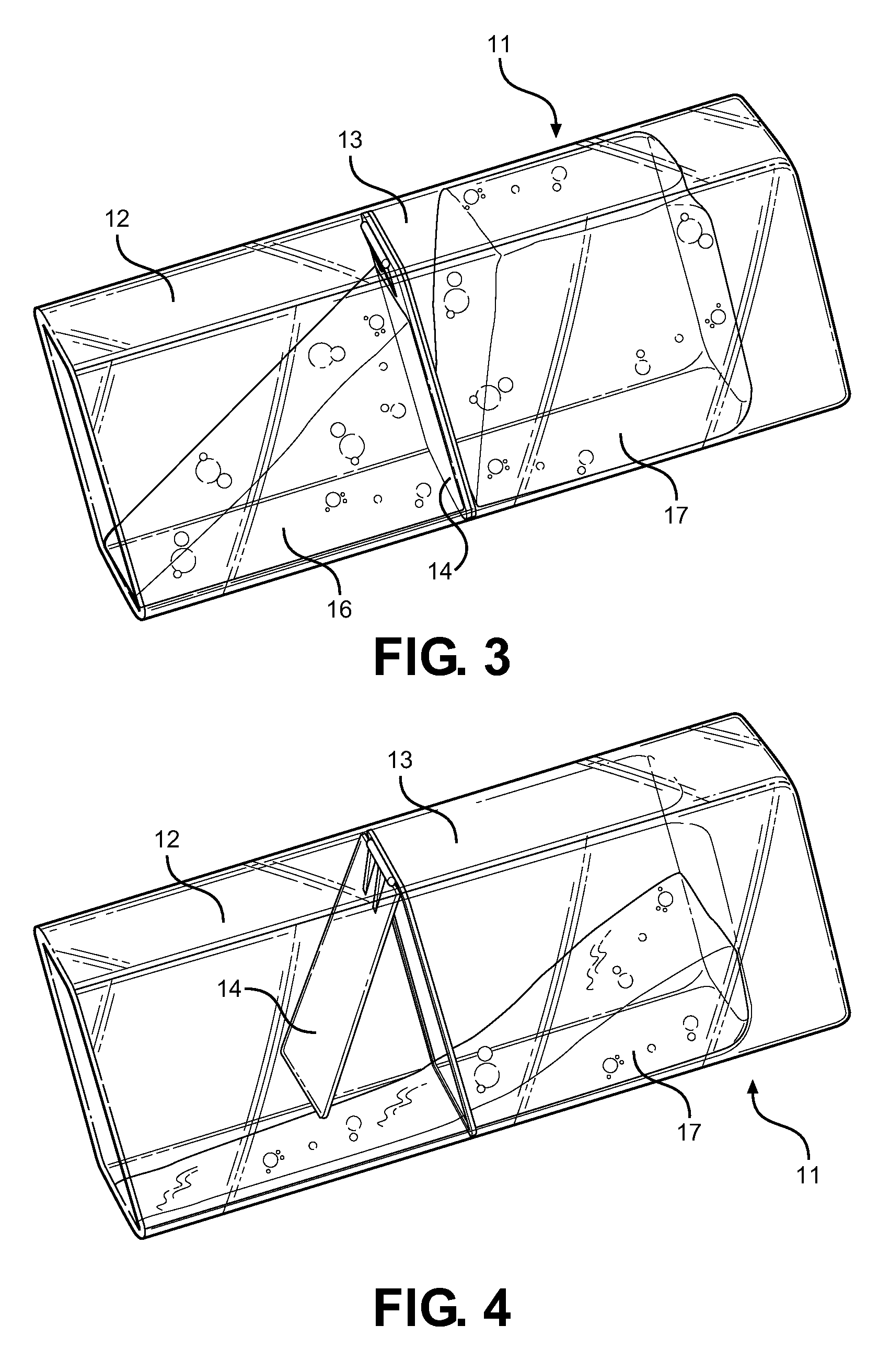
[0028]Referring now to FIG. 1, there is shown a dual-chambered beverage container in the form of a shot glass. The shot glass 11 has four walls and a bottom, defining an interior space. A unique feature of the shot glass is the bi-section of the interior space via a divider flap 14 that is hingedly secured to one interior wall. This bisection separates the interior space into an upper chamber 12 and a bottom chamber 13. When the divider fl...


PUM


Abstract

A dual-chambered beverage container in the form of a shot glass. The interior of the glass is bisected via a hinged divider flap, creating two separate chambers within the glass. The upper chamber holds a first beverage, preferably a shot of hard liquor, while the bottom chamber holds a volume of a second beverage, such as soda or juice. When the shot glass is in a resting position, the divider flap is closed, segregating the beverages in their respective chambers. A user begins to drink the first beverage, the hinged diver flap will slowly swing open, allowing the second beverage to flow out of the bottom chamber, through the upper chamber, and into the user's mouth. Thus the user experiences the taste of the shot of hard liquor only briefly before consuming the chaser beverage.

Description

CROSS REFERENCE TO RELATED APPLICATION[0001]This application claims the benefit of U.S. Provisional Application No. 61 / 565,265 filed on Nov. 30, 2011, entitled “ContraShot.” This provisional patent application is incorporated here by reference in its entirety to provide continuity of disclosure.BACKGROUND OF THE INVENTION[0002]1. Field of the Invention[0003]The present invention relates to a multi-chambered beverage container. More specifically, it relates to a shot glass having two chambers separated by a hinged divider. A first beverage can be poured in the bottom chamber, and a second beverage poured into the upper chamber. The beverage container will be appreciated by bar patrons who enjoy drinking a “chaser” beverage after ingesting a shot of hard liquor.[0004]Shots of liquor are commonly consumed by bar patrons who are interested in trying new liquors or consuming a higher proof drink. Hard liquors often have a harsh taste that leaves a burning sensation in the mouth of a user...

Claims


Application Information

Patent Timeline
Patent Type & Authority Patents(United States)
IPC IPC(8): B65D25/04B65D57/00B65D85/72A47G19/22
CPCA47G19/2205
Inventor MICHAELS, PAUL
Owner MICHAELS PAUL
Learn More