Power slider

a slider and slider technology, applied in the field of sliders, can solve the problems of abnormal noise, transmission of vibration between the gearbox and the screw-rod support rail cannot be sufficiently suppressed, etc., and achieve the effect of not generating abnormal nois

Active Publication Date: 2014-05-27
TOYOTA BOSHOKU KK
View PDF19 Cites 12 Cited by
  • Summary
  • Abstract
  • Description
  • Claims
  • Application Information

AI Technical Summary

Benefits of technology

[0008]The present invention has been devised with consideration of the above-described problems and achieves a power slider in which a gearbox favorably conforms to (follows) the undulations that occur in the rotation of the screw rod, wherein transmission of vibration between the gearbox and the screw-rod support rail can be adequately suppressed, and does not generate abnormal noise.
[0009]The present invention has been devised with a focus on providing a resilient member and placing this resilient member into a space between the mounting-bolt through-hole of the gearbox and the mounting bolt, therefore, since this resilient member absorbs undulations that occur during the rotation of the screw rod while allowing for movement of the mounting bolt within the mounting-bolt through-hole, the gearbox can conform to the undulations that occur during the rotation of the screw rod and can suppress the transmission of vibration between the gearbox and the screw-rod support rail; and furthermore, since the mounting bolt does not come in contact with the wall surface of the gearbox in which the mounting-bolt through-hole is formed, abnormal noise can be prevented from occurring.
[0015]According to the present invention, a power slider can be achieved in which a gearbox favorably conforms to undulations that occur in the rotation of the screw rod, transmission of vibration between the gearbox and the screw-rod support rail can be adequately suppressed, and abnormal noise is not generated.

Problems solved by technology

However, according to the inventors of the present invention, since a slight amount of space (clearance) is provided between the mounting-bolt through-holes and the mounting bolts, the gearbox cannot sufficiently conform to the undulations that occur in the rotation of the screw rod (i.e., eccentrical rotation with respect to the ideal rotational axis of the screw rod), so that the transmission of vibrations between the gearbox and the screw-rod support rail cannot be sufficiently suppressed.
Furthermore, there is the possibility of abnormal noise occurring when the mounting bolts contact the wall surface of the mounting-bolt through-holes of the gearbox.

Method used


Image

  • Power slider
  • Power slider
  • Power slider

Examples


Embodiment Construction

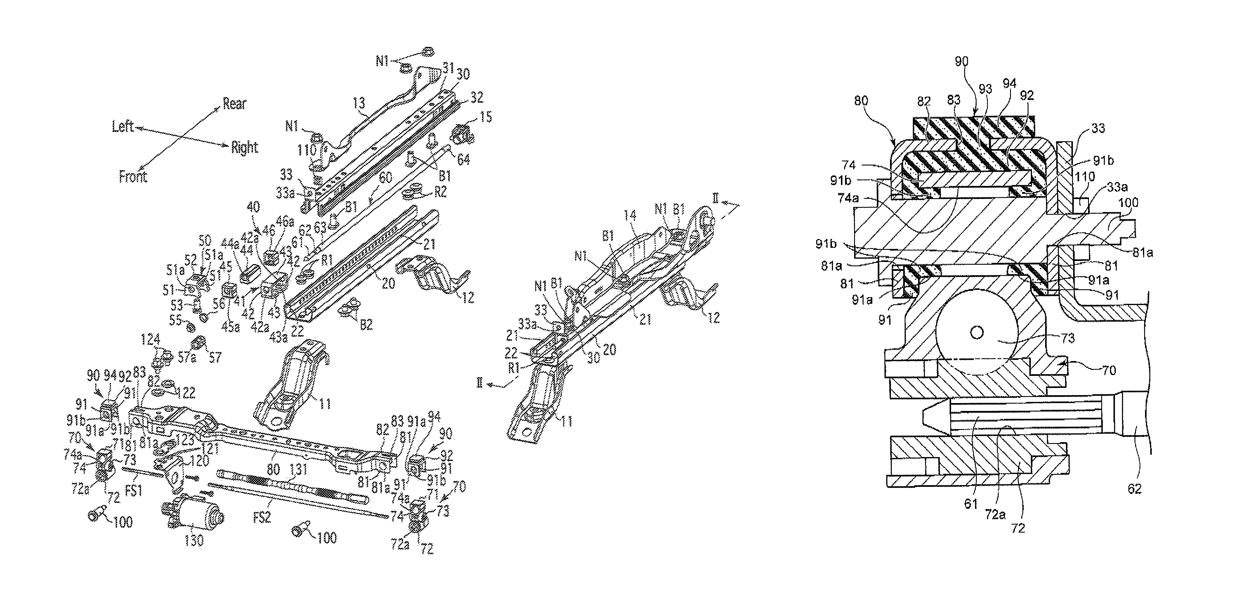
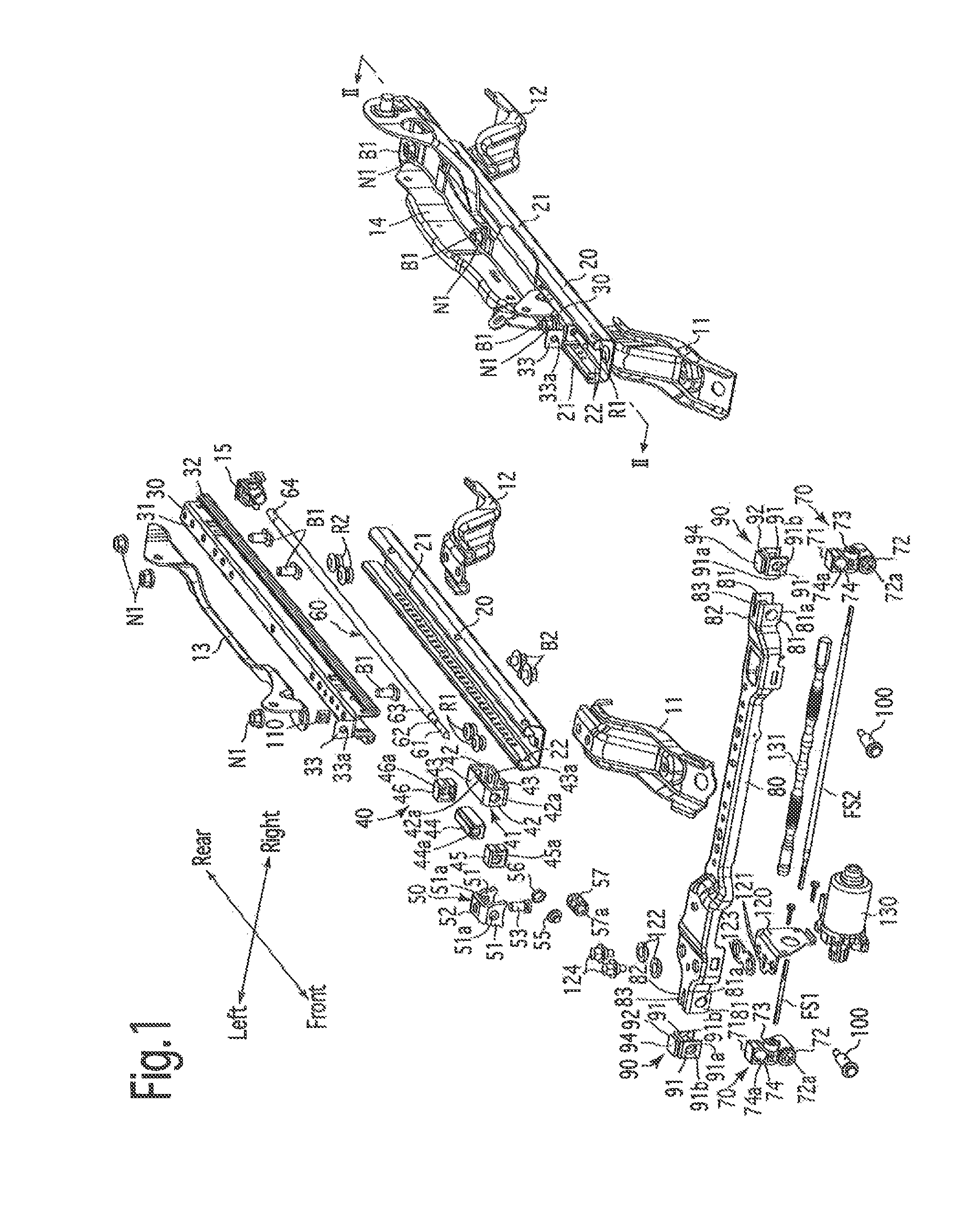
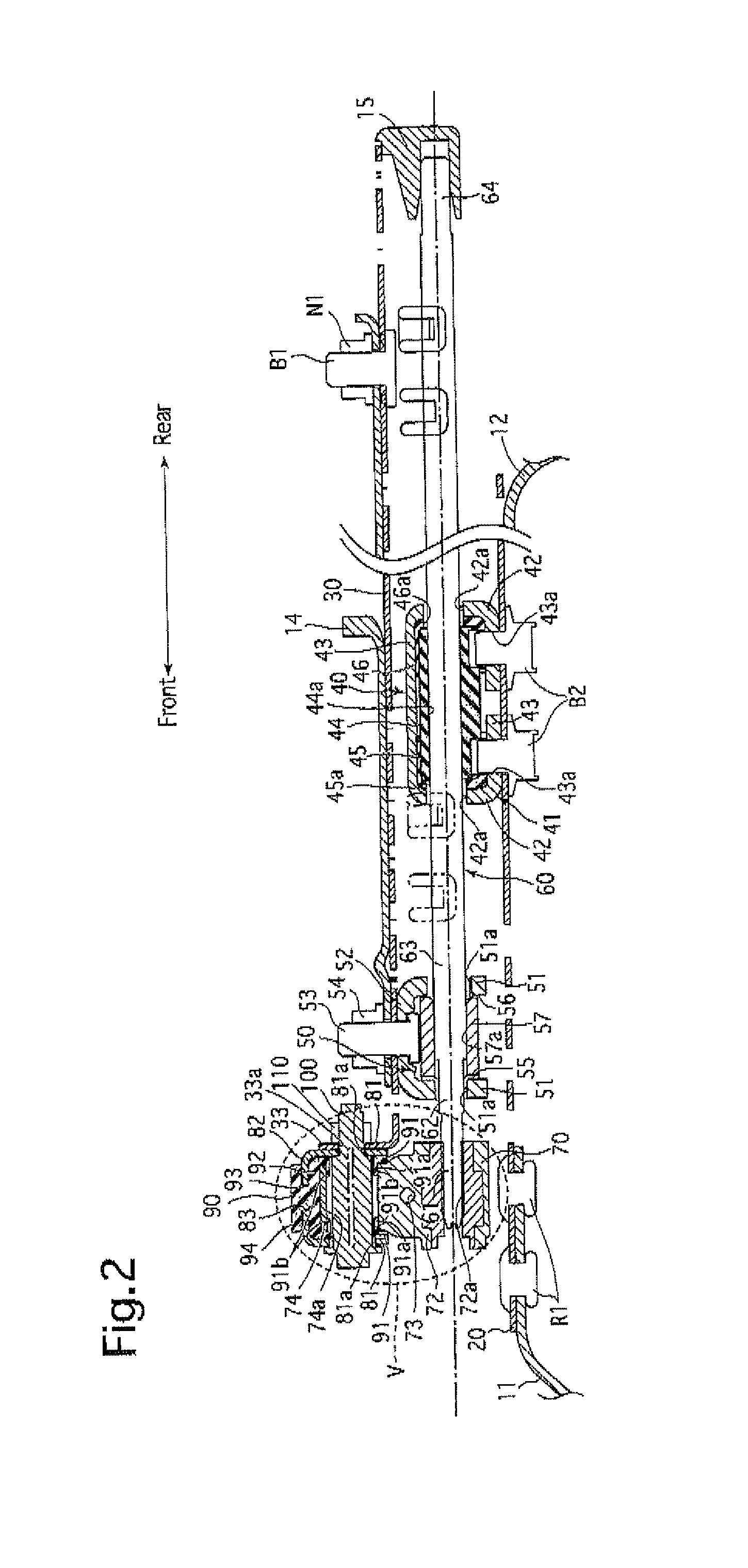
[0023]An embodiment of a power slider to which the present invention is applied will be hereinafter described with reference to FIGS. 1 through 4. The front / rear directions and left / right directions referred to in the following descriptions signify the directions as indicated by arrows in the drawings.

[0024]A front bracket 11 and a rear bracket 12, which constitute a pair of brackets, are fixed onto a floor inside a vehicle (not shown) so that one (left) pair of front and rear brackets 11 and 12 are arranged on the left side on the floor and another (right) pair of front and rear brackets 11 and 12 are arranged on the right side on the floor. The upper surfaces of the left and right pairs of front and rear brackets 11 and 12 are fixed to underside surfaces of left and right lower rails (feed-nut support rails) 20, at the front and rear ends thereof by rivets R1 and R2, respectively. The lower rails 20 are each formed as a metal channel member that linearly extends in the front / rear ...


PUM


Abstract

A power slider includes a lower rail and an upper rail which are engaged with each other so as to be mutually slidable along each other, a screw rod which is rotatably supported on one of the lower rail and the upper rail, a feed nut which is supported on the other of the lower rail and the upper rail and is screw-engaged with the screw rod, and a gearbox which is supported on the one of the lower rail and the upper rail via a holder and which rotatably drives the screw rod. The gearbox is provided with a mounting bolt through-hole and is supported by the holder via a mounting bolt that is inserted through the mounting bolt through-hole. A resilient member is positioned in a space defined between the mounting bolt through-hole of the gearbox and the mounting bolt.

Description

BACKGROUND OF THE INVENTION[0001]1. Field of the Invention[0002]The present invention relates to a power slider for use, e.g., in a vehicle for slidably moving a vehicle seat.[0003]2. Description of Related Art[0004]Generally, a power slider comprises a lower rail, an upper rail that is engaged with the lower rail so as to be mutually slidably along each other, a screw rod (spindle) and a feed nut which are supported on one and the other of the lower rail and the upper rail, the feed nut being screw-engaged with the screw rod. The power slider is further provided with a gearbox, which rotatably drives the screw rod via a holding bracket (holder), on the rail which supports the screw rod (screw-rod supporting rail).[0005]The gearbox is provided with a mounting-bolt through-hole, and the gearbox is supported by the holding bracket (holder) via amounting bolt that is inserted through the mounting-bolt through-hole. Furthermore, the gearbox supports a rotational mechanism (including a w...

Claims


Application Information

Patent Timeline
Patent Type & Authority Patents(United States)
IPC IPC(8): F16M13/00
CPCB60N2/0705B60N2/0232F16F15/08B60N2/067B60N2/02246
Inventor KIMURA, AKIHIROENOKIJIMA, TOMOHIRO
Owner TOYOTA BOSHOKU KK
Why Eureka
Try Eureka