Image forming apparatus

a technology of image forming and forming parts, which is applied in the direction of electrographic process equipment, instruments, optics, etc., can solve the problems of user stretching, difficult for the user to pull the side door outward, and the side door is rather difficult to open from the front side of the apparatus, so as to achieve the effect of being easier to open to a user

Inactive Publication Date: 2014-05-27
CANON KK
View PDF12 Cites 5 Cited by
  • Summary
  • Abstract
  • Description
  • Claims
  • Application Information

AI Technical Summary

Benefits of technology

[0007]Thus, the primary object of the present invention is to ensure that a pair of pressure applying mechanisms with which the side door of an image forming apparatus is provided always and virtually simultaneously disengage from the main assembly of the apparatus, even if the side door is relatively large, in order to make it possible to provide an image forming apparatus, the side door of which feels more solid and easier to open to a user when the user opens the side door, than the side door of any of conventional image forming apparatus.

Problems solved by technology

In the case of a large image forming apparatus, that is, an image forming apparatus capable of handling a sheet of recording medium of a size A3, it is greater in size in terms of the front-to-rear direction, and therefore, its side door is rather difficult to open from the front side of the apparatus.
Therefore, as a user grasps the handle of the side door, which is at the middle of the door in terms of the front-to-rear direction, while standing in front of the image forming apparatus, the arm of the user becomes stretched, making it difficult for the user to pull the side door outward.
However, as a test version of this side door was tested, this proposal also turned out to be problematic.
Consequently, it made the tester feel nervous or even uncomfortable as the tester opened the side door.

Method used


Image

  • Image forming apparatus
  • Image forming apparatus
  • Image forming apparatus

Examples


embodiment 1

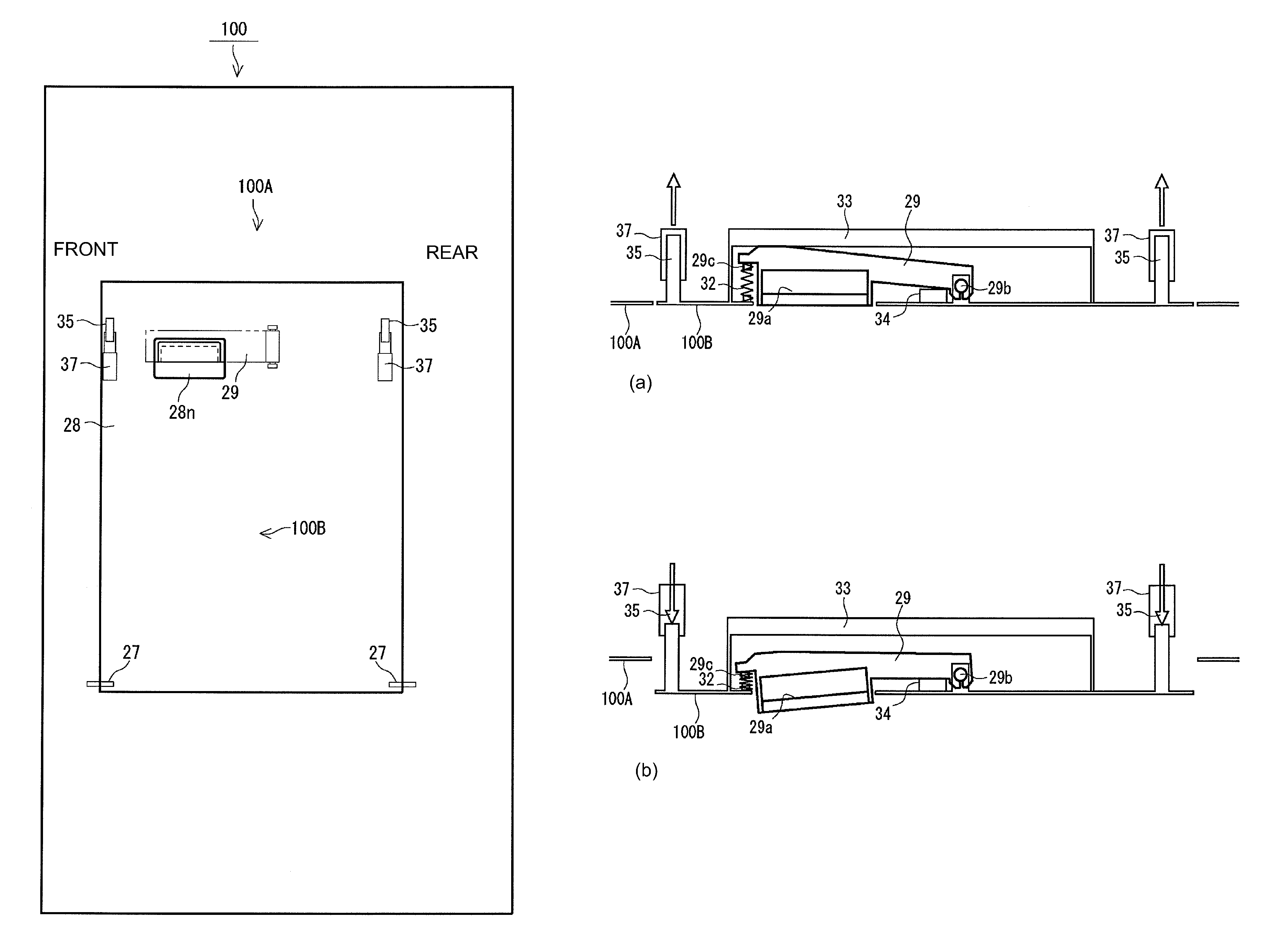
[0065]FIG. 8 is a drawing for describing the positioning of the hand lever 29 relative to the door unit frame 28. FIG. 9 is a perspective view of the hand lever 29. FIG. 10 is a schematic sectional view of the essential portions of the hand lever 29, which are on the inward side of the door unit 100B. FIG. 11 is a drawing for describing the force to which the door unit 100B is subjected as the hand lever 29 is pulled by a user, by the latch 29a.

[0066]Referring to FIG. 8, the latch 29a of the hand lever 29, which is to be pulled by a user when the user wants to open the door unit 100B, is positioned very close to the front end of the door unit frame 28. Thus, the user can open the door unit 100B while remaining in the same position and attitude as those in which the user was when the user confirmed the message on the display of the control panel while standing upright in front of the apparatus main assembly 100A. The latch 29a of the hand lever 29, which the user is to pull to opera...


PUM


Abstract

An image forming apparatus includes a main assembly; a door member which supports one of roller members constituting a feeding nip for a recording material and which is rotatable about an axis parallel with said roller members in a sidewise direction of said main assembly to open said feeding nip; a pair of urging mechanisms which are provided at opposite end portions of said door member with respect to a front-rear direction of said main assembly and which fix said door member to said main assembly so as to be capable of opening and closing said door member, said urging mechanism urging said door member toward said main assembly in a state that said door member is closed; and an operating member provided with a grip for manual opening of said door member, said grip being disposed in a position nearer to a front side than a center portion position of said door member with respect to the front-rear direction, and said operating member being rotatably supported in a position nearer to a rear side than a center position between urging mechanisms.

Description

FIELD OF THE INVENTION AND RELATED ART[0001]The present invention relates to an image forming apparatus whose side door can be opened to expose the recording medium conveyance nip of the image forming apparatus. More specifically, it relates to the structure of the handle with which the side door of the image forming apparatus is provided to improve the apparatus in terms of the operation for disengaging the toggle latches of the like of the side door located at the front and rear ends of the side door.[0002]An image forming apparatus designed to form a toner image, transfer the toner image onto recording medium, and fix the toner image to the recording medium by applying heat and pressure to the toner image has been widely in use. Normally, an image forming apparatus of this type is provided with a side door for removing the jammed recording medium in the nip between a pair or pairs of recording medium conveyance rollers of the apparatus, and is structured so that the side door can...

Claims


Application Information

Patent Timeline
Patent Type & Authority Patents(United States)
IPC IPC(8): G03G21/00
CPCG03G2215/00544G03G21/1633G03G2221/169G03G2221/1675
Inventor TANABE, YUICHIKOBAYASHI, TAKAHIRO
Owner CANON KK
Why Eureka
Try Eureka