
Cordless blind and operator device

a cordless blind and operator technology, applied in the direction of door/window protective devices, shutters/movable grilles, wing arrangements, etc., can solve the problems of not being able to keep the bottomrail at the desired location, the cord collector is not suitable for installation, and the cord collector is not suitable for maintenance, so as to maintain the tension effect of the cord collector

Active Publication Date: 2014-06-03
HUNTER DOUGLAS INC
View PDF48 Cites 16 Cited by
  • Summary
  • Abstract
  • Description
  • Claims
  • Application Information

AI Technical Summary

Benefits of technology

This patent describes a cordless blind that uses a spring motor to keep the blinds in a certain position. The blinds move smoothly and can be locked to keep them in place. This blind is easy to operate and can be placed in any position between fully raised and fully lowered. The main technical effect of this invention is its ease of use and flexibility in positioning the blinds.

Problems solved by technology

In recent years the art has been concerned that cords, particularly looped cords, pose a strangulation threat to children who may become entangled in the cords.
Furthermore, Coslett's blind is not suitable for installation in an orientation in which one rail is fixed at the top of the window frame as is done for most building windows.
Consequently, it is not possible to keep the bottomrail at the desired location without adjusting or replacing the spring motors.
If such a blind is installed in a tall window many people would be unable to reach a fully raised blind without climbing on a ladder or chair.
Even if the blind were in a standard window, short people would not be able to fully raise the blind without using a ladder.
Operators would also have difficulty fully raising such a blind if a couch or other furniture were in front of the window.

Method used


Image

  • Cordless blind and operator device
  • Cordless blind and operator device
  • Cordless blind and operator device

Examples


first embodiment

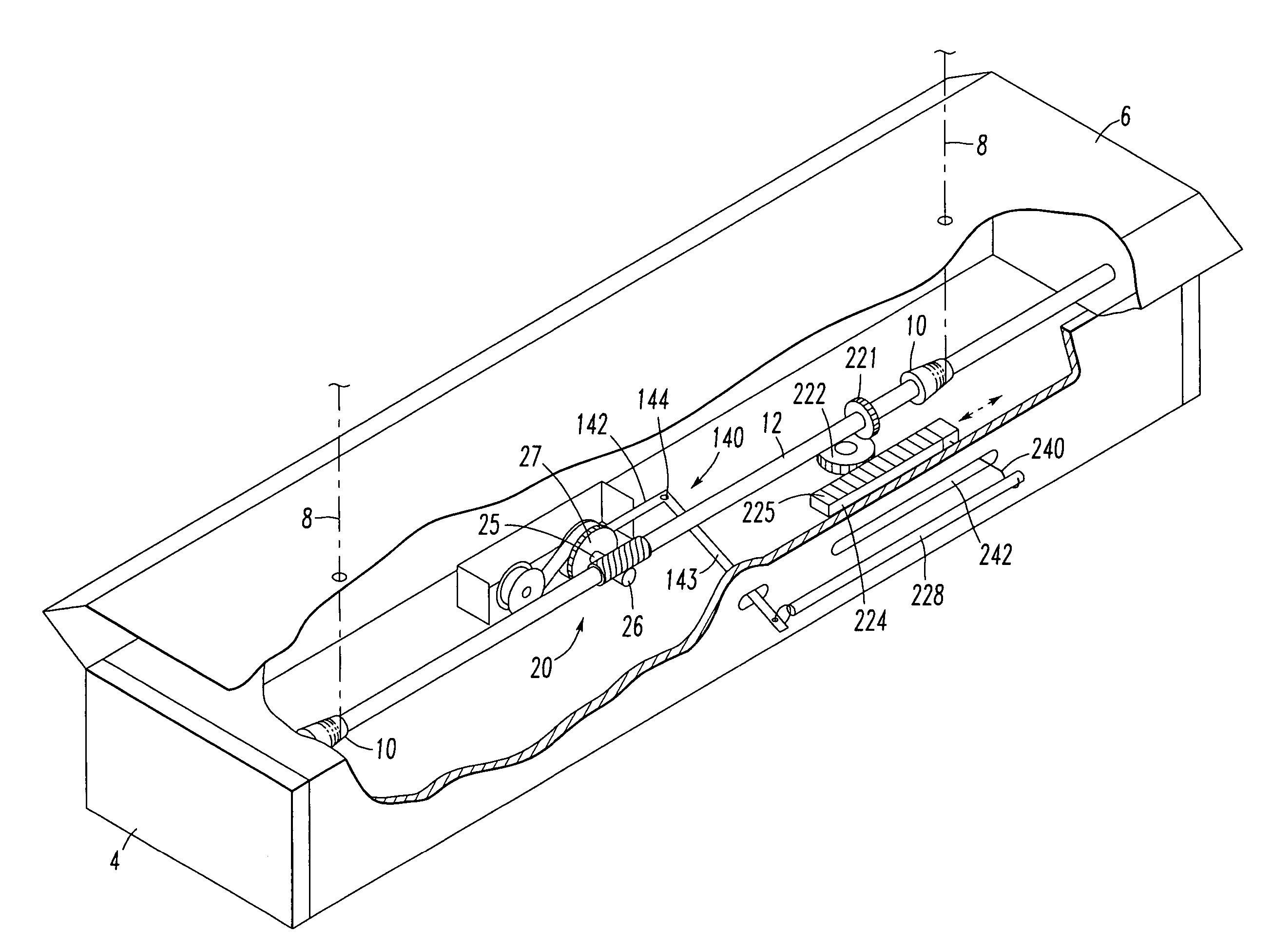
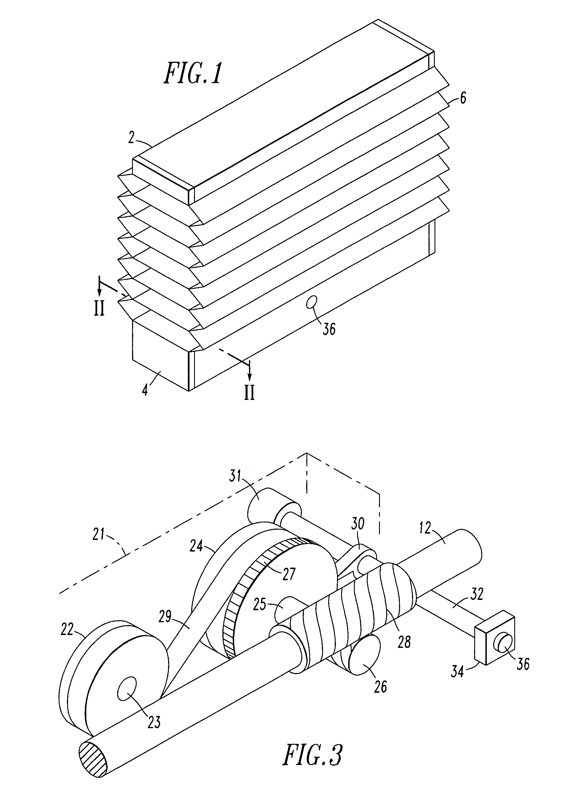
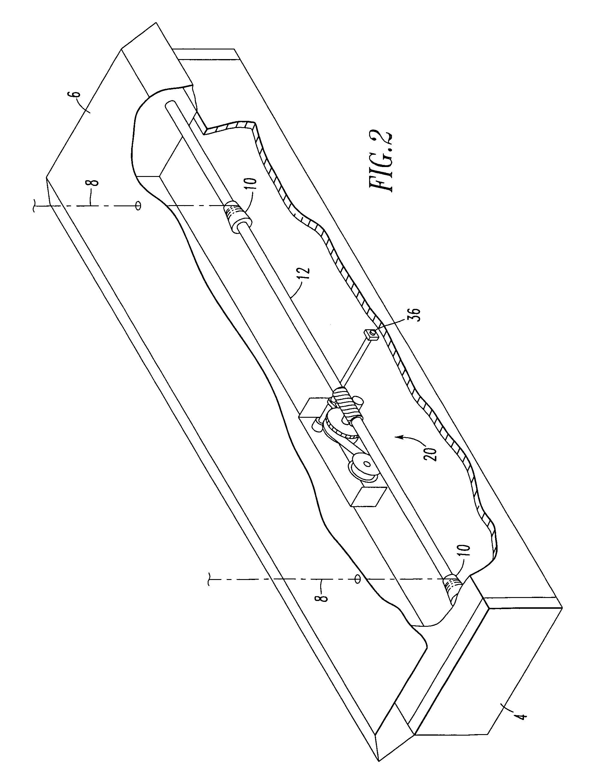
[0053]Another spring motor configuration is illustrated in FIG. 5. This spring motor 50 has three take-up drums 52 each carrying a spring that is also connected to an associated storage drum 54. A link 56 connects the take up drums together. The lift cords are wound on spools connected to a respective storage drum. This spool and take up drum configuration is similar to the spool 42 and take up drum 24 shown in FIG. 4. In the embodiment of FIG. 5 the spools are behind the take up drums and thus are not visible in the figure. A spring 59 is connected between each storage drum 54 and take up drum 52 pair. This spring can be any of the springs described as suitable for use in the first embodiment and operates in the same manner. A lock mechanism (not shown) is connected to at least one of the storage drums or spool. The lock mechanism operates in the same manner as the lock mechanism described in the embodiment of FIGS. 1, 2 and 3.

[0054]Yet another spring motor configuration is shown i...

second embodiment

[0056]Second and third present preferred embodiments of my cordless blind utilize a cord lock in conjunction with one or more spring motors. The spring motor and lock mechanism for the second embodiment shown in FIG. 8 has a single spring motor with a take up drum 24 and storage drum 22. A cord collector spool 44 is carried on the same axle 42 that carries take up drum 24. Consequently, the spring motor will try to wind the lift cords 8 onto the spool 24. The lift cords are routed through a cord lock 46. When the cord lock is in a locked position, the lift cords cannot be wound onto the spool. When the cord lock is unlocked the spring motor will wind the lift cords onto the spool raising the blind. Furthermore, while the cord lock is unlocked a user could pull the bottomrail down overcoming the force of the spring motor and lowering the blind. The cord lock 46 may contain a rotary-cam lock mechanism that acts directly on the cords. The third present preferred embodiment has a bottom...


PUM


Abstract

A cordless blind contains a lift mechanism, such as one or more spring motors, one or more cord collectors and a lock mechanism. An operator device such as a cord or wand is connected to the lift mechanism and is movable relative to the bottomrail. When the bottomrail is a selected distance from the headrail a portion of the cord or wand will move away from the bottomrail. The selected distance corresponds to the height of the bottomrail at which it is difficult for an operator to reach the bottomrail. The released cord or wand will enable the user to operate a lock mechanism in the bottomrail or move the bottomrail.

Description

CROSS REFERENCE TO RELATED APPLICATION[0001]This application is a Continuation-in-part of U.S. patent application Ser. No. 10 / 704,851, file Nov. 10, 2003 now U.S. Pat. No. 7,117,919. U.S. patent application Ser. No. 10 / 704,851 was a Continuation-in-part of U.S. patent application Ser. No. 09 / 815,403, filed on Mar. 22, 2001, now U.S. Pat. No. 6,644,372.FIELD OF INVENTION[0002]The invention relates to a lock mechanism for raising and lowering cordless window blinds, such as pleated shades, roman shades, and venetian blinds.BACKGROUND OF THE INVENTION[0003]Venetian type blinds have a series of slats hung on ladders that extend from a headrail to a bottomrail. In most venetian blinds a pair of lift cords is provided each having one end attached to the bottomrail and then passing through elongated holes in the slats up to and through the headrail. When the lift cords are pulled downward the blind is raised and when the lift cords are released the blind is lowered. A cord lock is usually ...

Claims


Application Information

Patent Timeline
Patent Type & Authority Patents(United States)
IPC IPC(8): A47H5/00
CPCE06B9/322
Inventor JUDKINS, REN
Owner HUNTER DOUGLAS INC
Learn More