Method for stabilizing plasma ignition

a plasma ignition and stabilizing technology, applied in the field of stabilizing plasma ignition, can solve the problems of high rf power, inability to stabilize plasma ignition, so as to reduce the failure rate of ignition

Active Publication Date: 2014-06-03
ASM IP HLDG BV
View PDF22 Cites 379 Cited by
  • Summary
  • Abstract
  • Description
  • Claims
  • Application Information

AI Technical Summary

Benefits of technology

[0010]Some embodiments provide a method for stabilizing plasma ignition in a continuous process conducted on a substrate, comprising: (i) applying a spike of RF power between an upper electrode and a lower electrode on which the substrate is placed, wherein the spike starts from zero power, jumps to a spike power, and then drops to a base power which is so low as to cause plasma ignition failure; and (ii) continuously applying RF power at the base power between the upper and lower electrode for a duration substantially longer than a duration of the spike to process the substrate, wherein the spike is such that ignition failure is reduced.
[0012]Due to the spike of PR power application, plasma ignition failure can significantly be reduced without causing a substantial change to a film.

Problems solved by technology

For example, high RF power can improve quality of film; however, in some applications, extremely low RF power is required.
However, if diffusion occurs during the film-forming process, foreign matter will inevitably diffuse to areas where diffusion of the foreign matter is not desired.
A phosphosilicate glass (PSG) process has problems similar to the above when high RF power is applied.
Devices with the oxidized underlying layer do not possess desired characteristics.
As a result, a photoresist with a desirable size cannot be obtained.
On the other hand, application of low RF power causes problems.
If RF power is low, the effects by power loss in RF transmitter circuits, sensitivity to matching box positioning, and / or sensitivity to changes in the atmosphere in a reaction chamber (e.g., due to changes in thickness of depositing films) become more serious.
Accordingly, sometimes voltage does not reach the firing voltage, causing plasma ignition failure or shortening plasma treatment.
As a result, the expected processing results (e.g., film thickness or uniformity) cannot be obtained.

Method used


Image

  • Method for stabilizing plasma ignition
  • Method for stabilizing plasma ignition
  • Method for stabilizing plasma ignition

Examples


examples

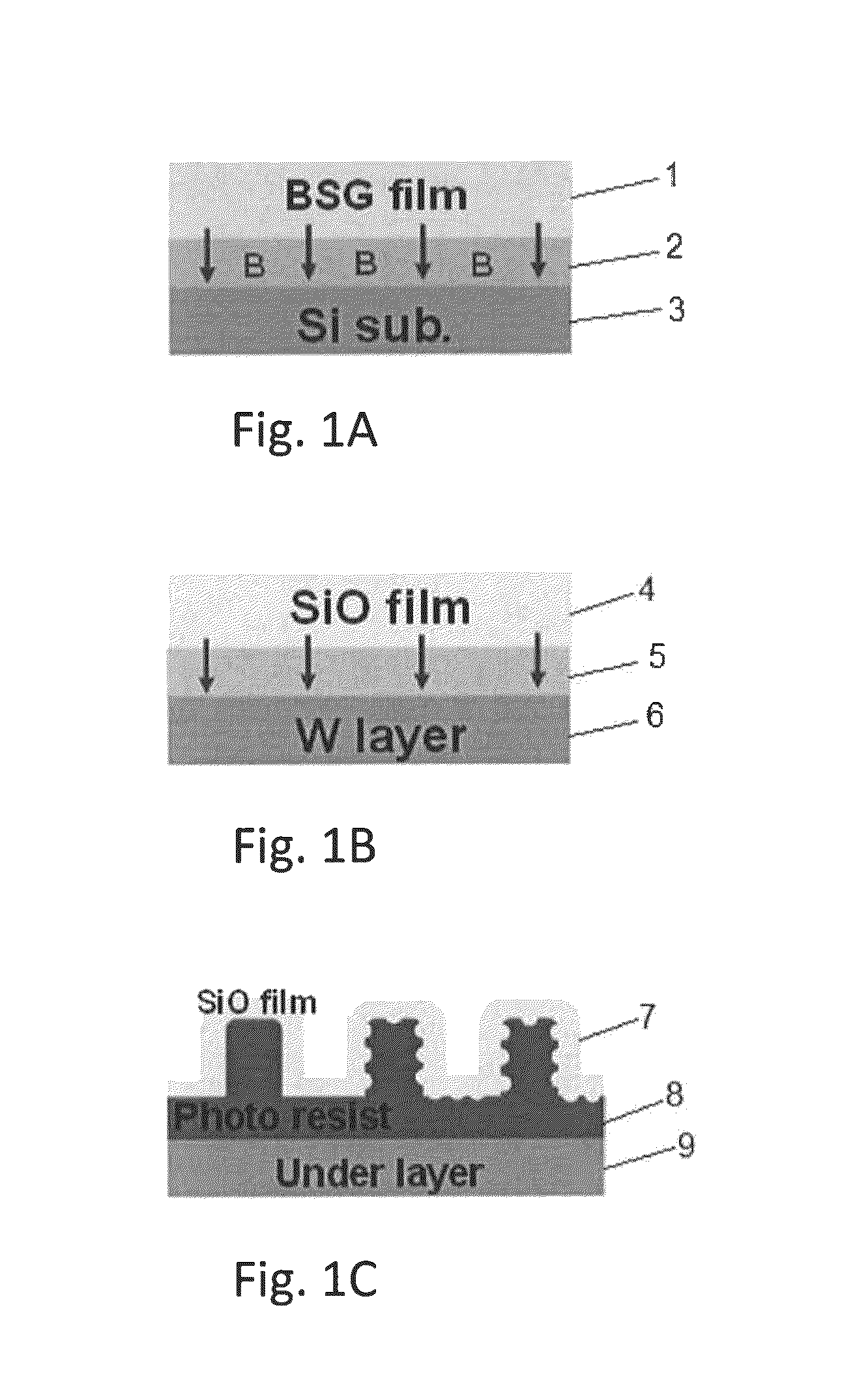
[0057]A semiconductor substrate (300 mm in diameter) was loaded onto a susceptor having a diameter of 325 mm of an apparatus illustrated in FIG. 4 for PEALD of borosilicate glass (BSG), and a film of BSG was deposited on the substrate under the conditions as follows:

[0058]PEALD for BSG:

[0059]Precursor: BDEAS, TEOB

[0060]Precursor inflow pressure: 400 Pa

[0061]Substrate temperature: 300° C.

[0062]Carrier gas flow: 2.0 SLM (continuous)

[0063]Reactant gas flow: 0.5 SLM (continuous)

[0064]Precursor supply time per cycle: 0.3 seconds

[0065]Purge time after precursor pulse: 1.0 seconds

[0066]RF frequency: 13.56 MHz

[0067]RF Plasma exciting time per cycle: 0.2 seconds

[0068]Purge time after RF application cycle: 0.1 seconds

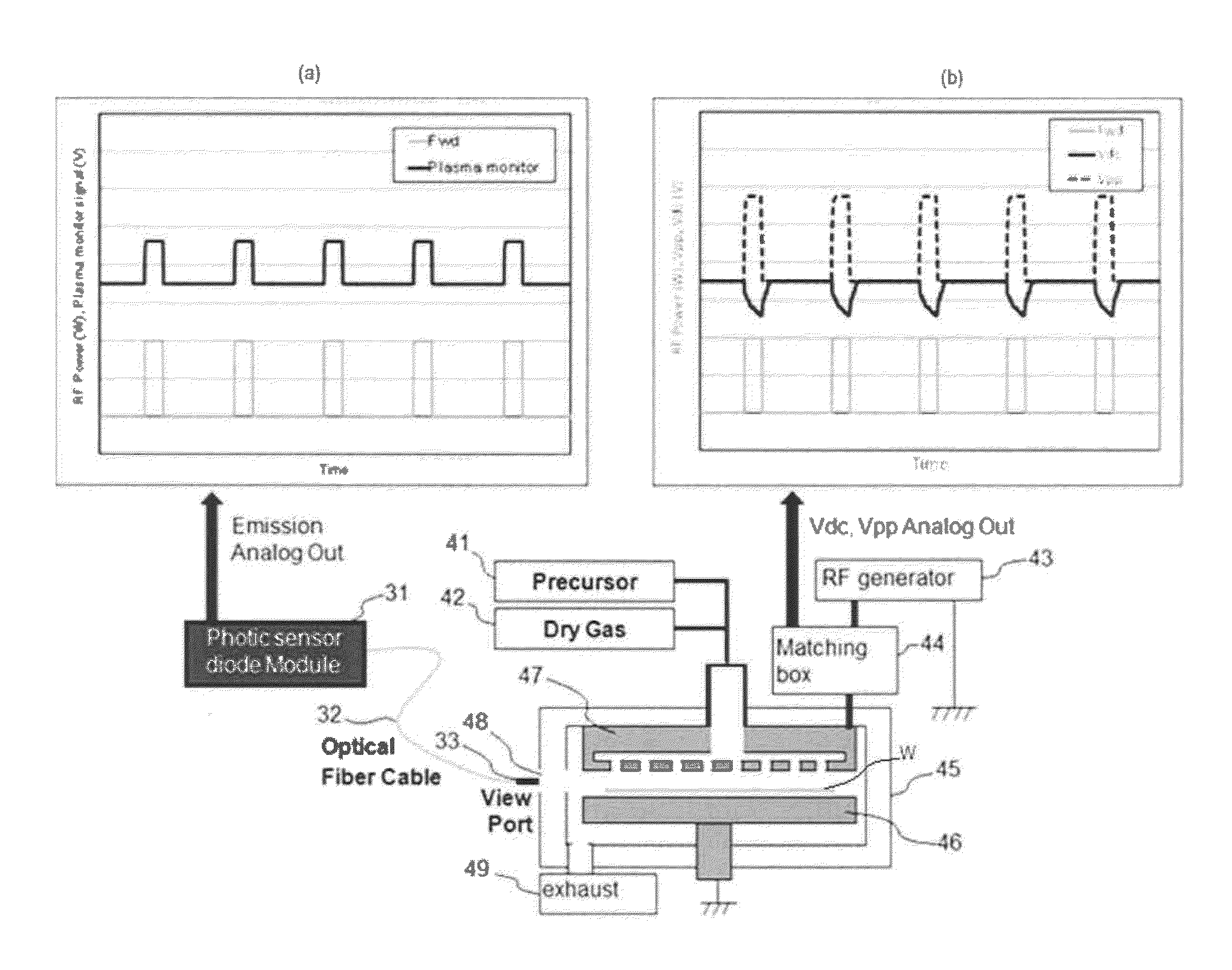
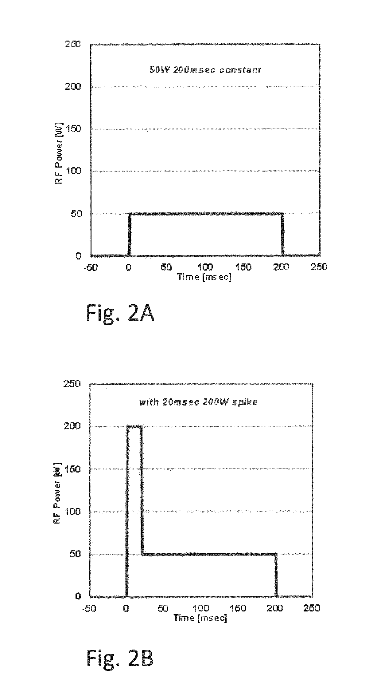
[0069]Each cycle of RF power application was controlled based on FIG. 2B using a program executing the sequences illustrated in FIGS. 10 and 11 under the conditions shown in Table 2 below. Under the respective conditions, a plasma ignition failure ratio (a ratio of the number of ...


PUM


Abstract

A method for stabilizing plasma ignition in a continuous process conducted on a substrate, includes: applying a spike of RF power between an upper electrode and a lower electrode on which the substrate is placed, wherein the spike starts from zero power, jumps to a spike power, and then drops to a base power which is so low as to cause plasma ignition failure; and continuously applying RF power at the base power between the upper and lower electrode for a duration substantially longer than a duration of the spike to process the substrate. The spike is such that ignition failure is reduced.

Description

BACKGROUND[0001]1. Field of the invention[0002]The present invention generally relates to a method of processing a substrate with plasma by, e.g., plasma-enhanced atomic layer deposition (PEALD) or other plasma-enhanced deposition, particularly to a method for stabilizing plasma ignition in such a process.[0003]2. Description of the Related Art[0004]In PEALD processes, for example, RF power is an important parameter for controlling film quality and characteristics. For example, high RF power can improve quality of film; however, in some applications, extremely low RF power is required. The following three applications are typical examples.[0005]FIG. 1A is a schematic view illustrating a borosilicate glass (BSG) process for solid state diffusion (SSD). The reason that low RF power is required in this process is that if high RF power is applied, dopant implantation into a Si substrate occurs at a film-forming stage by ion bombardment. As illustrated in FIG. 1A, when a BSG film 1 is fo...

Claims


Application Information

Patent Timeline
Patent Type & Authority Patents(United States)
IPC IPC(8): H05H1/46
CPCH01J37/32137H01J37/32091H05H1/46
Inventor NAKANO, RYUMAKINO, TSUTOMUTAKAMIZAWA, HISASHI
Owner ASM IP HLDG BV
Why Eureka
Try Eureka