Image forming apparatus
a technology of image forming apparatus and rotating drum, which is applied in the direction of couplings, hoisting equipment, instruments, etc., can solve the problems of non-uniform non-uniform scanning line pitch, and inability to achieve uniform rotation so as to reduce the weight of the image forming apparatus, suppress the minute speed fluctuation of the photosensitive drum, and reduce the effect of forming apparatus
- Summary
- Abstract
- Description
- Claims
- Application Information
AI Technical Summary
Benefits of technology
Problems solved by technology
Method used
Image
Examples
embodiment 1
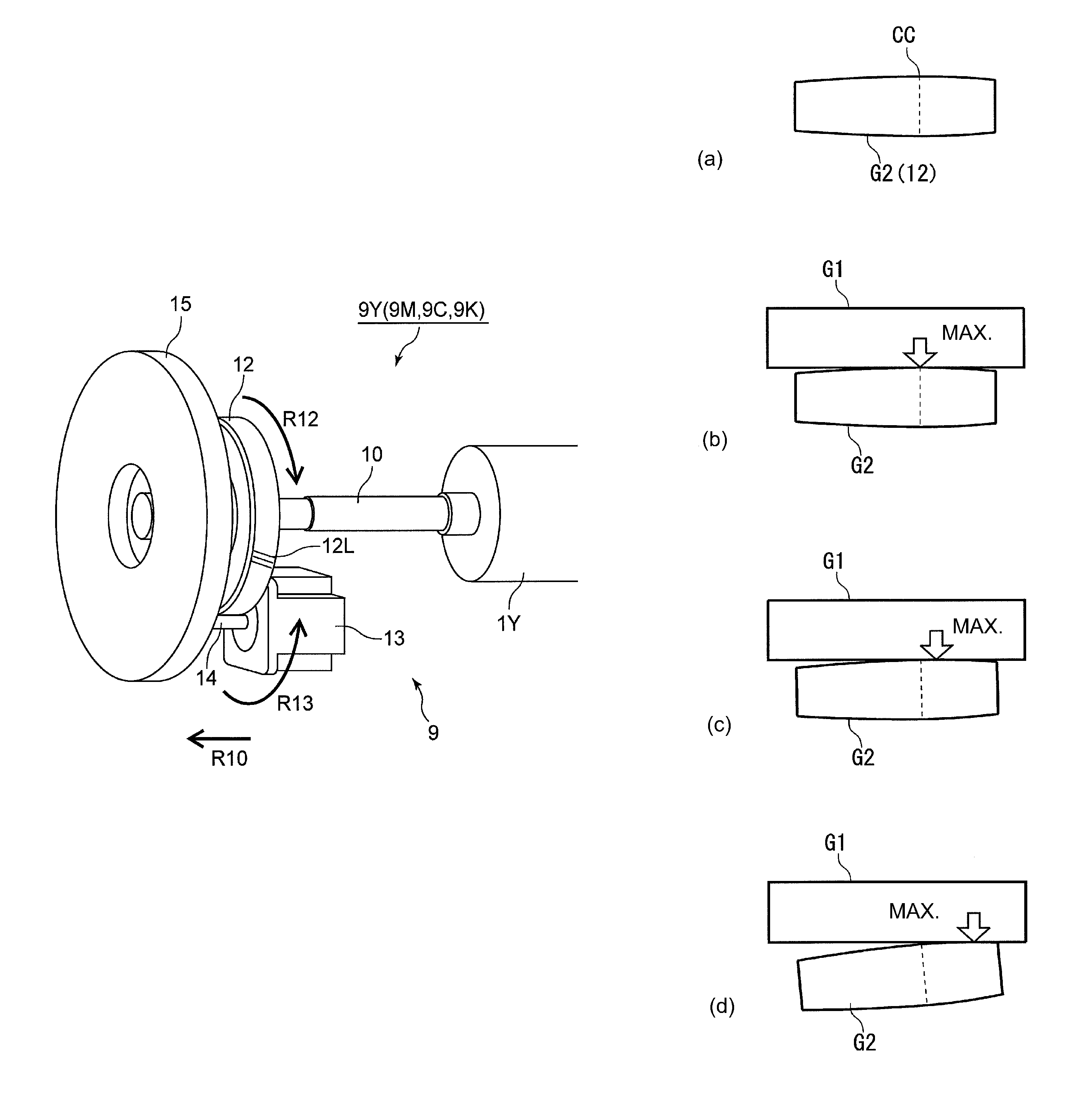
[0076]FIG. 8 is a partly enlarged view of the driving system of the photosensitive drum. FIG. 9 is a perspective view of a driven gear which has been subjected to asymmetrical crowning. Parts (a) to (d) of FIG. 10 are illustrations of end tooth bearing of the driven gear which has been subjected to the asymmetrical crowning. FIG. 11 is a graph showing a measurement result of a load torque of a drum motor. Incidentally, in this embodiment, the helical gear is used but with reference to FIGS. 9 and 10, asymmetrical crowning will be described by using the spur gear in place of the helical gear.
[0077]As shown in FIG. 8, the drum gear 12 which has been subjected to the crowning and the motor gear 14 which has not been subjected to the crowning are engaged with each other, so that the torque of the motor 13 is transmitted to the drum gear shaft 10. In this embodiment, as a result of analysis described later, it was turned out that a side where a position of the tooth surface of the drum g...
embodiment 2
[0106]FIG. 14 is an illustration of a structure of an intermediary transfer unit.
[0107]As shown in FIG. 14, a supporting casing 56 of an intermediary transfer unit 50 rotatably supports a tension roller 52 and a driving roller 54. The driving roller 54 for driving an intermediary transfer belt 55 which is an example of a belt member is driven by a motor driving mechanism 57. The motor driving mechanism 57 rotates the driving gear 54 by engaging a motor gear 64 of a motor 63 with a roller gear 62 fixed to a roller shaft 60 to transmit an output torque of the motor 63 to the roller shaft 60.
[0108]The roller shaft 60 is rotatably supported by the supporting casing 56 by using a bearing 68. The motor 63 is fixed to the supporting casing 56, and the motor gear 64 which is an example of the driving gear is directly formed on the motor driving shaft. The roller gear 62 which is an example of the driven gear is engaged with the motor gear 64 and is rotated integrally with the driving roller...
embodiment 3
[0112]In Embodiment 1, the suppression of the rotational speed fluctuation of the photosensitive drum attached to the casing structure of the image forming apparatus was described. However, the present invention is also applicable to a driving portion of the photosensitive drum attached to the casing structure of a process cartridge. In either case, the amount of the steady alignment error may only be required to be estimated by using the above-described analysis method to determine the shift amount of the crowning center depending on the result of the estimation.
[0113]Further, in the case of the resin molding, there is no need to effect the crowning by cutting of the material and therefore it is possible to inexpensively manufacture the gear which has been subjected to the crowning. Further, the gear of the resin material has the Young's modulus smaller than that of the metal shaft, so that the contact area by the compression deformation is increased and thus the speed fluctuation ...
PUM
 Abstract
Description
Claims
Application Information
 - R&D
- Intellectual Property
- Life Sciences
- Materials
- Tech Scout
- Unparalleled Data Quality
- Higher Quality Content
- 60% Fewer Hallucinations
Browse by: Latest US Patents, China's latest patents, Technical Efficacy Thesaurus, Application Domain, Technology Topic, Popular Technical Reports.
© 2025 PatSnap. All rights reserved.Legal|Privacy policy|Modern Slavery Act Transparency Statement|Sitemap|About US| Contact US: help@patsnap.com


