Luminance control for illumination devices

a technology of illumination device and control circuit, which is applied in the direction of electric variable regulation, process and machine control, instruments, etc., can solve the problems of inability to accept some applications, the brightness produced by fixed current can change over time, and the lamp will just get dimmer, so as to prolong the longevity of the reference led, reduce the cost and complexity of the optical feedback circuit typically used to monitor the brightness of the illumination devi

Active Publication Date: 2014-06-10
LUTRON TECH CO LLC
View PDF163 Cites 58 Cited by
  • Summary
  • Abstract
  • Description
  • Claims
  • Application Information

AI Technical Summary

Benefits of technology

[0012]The first embodiment described herein uses an additional light detector, such as a photo-detector, to measure the ratio of optical power produced by the reference LED over the optical power produced by the illumination LEDs used for illumination. Such a photo-detector can be, for example, a simple and inexpensive silicon diode. And the reference LED can be, for example, a blue LED. Because the optical output power from a blue LED is relatively insensitive to temperature and because the photo-detector is measuring ratios of optical power, temperature and other conditions that can affect the current induced in the silicon diode by incident light can effectively be ignored. As such, these temperature and other operating conditions do not have to be compensated for, which simplifies the optical feedback control circuitry and reduces cost.
[0013]The second embodiment described herein further reduces cost by using one or more of the illumination LEDs already within the LED illumination device to detect the power ratios, thereby eliminating the need for an additional photo-detector. For these embodiments, one or more of the illumination LEDs that are used for illumination are also used to detect the ratio of optical power produced by the reference LED over the optical power produced by the illumination LEDs. In these embodiments, the LEDs that provide illumination can also be configured in at least two separate chains that are controlled independently. A first LED chain (e.g., one or more LEDs) measures the ratio of light from the reference LED over the light produced by a second LED chain (e.g., one or more LEDs), and the second LED chain measures the ratio of light from the reference LED over the light produced by the first chain. As such the light produced by each LED chain can be measured and adjusted to a desired value, such as a fixed value, resulting in the combined light from both LED chains remaining at a fixed level.
[0015]Advantageously, the embodiments disclosed herein address problems in prior solutions with the addition of an LED to an illumination device that is then used as a reference light source. As such, the cost and complexity of the optical feedback circuitry typically used to monitor illumination device brightness can be reduced for some applications by the embodiments described herein.
[0016]An illumination device is provided in one embodiment. The illumination device comprises one or more illumination LEDs that are configured to provide illumination for the device during normal operation of the device. When the device is called upon to provide illumination, the illumination LEDs are active. The illumination device further comprises driver circuitry coupled to the illumination LEDs for driving the illumination LEDs during illumination operation of the device. At least one reference LED is also provided which operates only during test, but does not operate during normal illumination operation. Thus, the reference LED is used less frequently (i.e., only during test, but not during normal operation) which proves advantageous in extending the longevity of the reference LED providing operation as a reference output that does not significantly change throughout multiple tests.

Problems solved by technology

Although LEDs have many advantages over conventional light sources, such as incandescent and fluorescent light bulbs, a disadvantage of LEDs is that the brightness produced by a fixed current can change over time.
Unlike a conventional incandescent or fluorescent light bulb that typically fails catastrophically, a typical LED lamp will just get dimmer over time, which can be an issue if one lamp in an array of LED lamps has to be replaced before the others.
The new lamp typically will appear brighter than the rest, which may not be acceptable in some applications.
Although most commercially available LED lamps today do not compensate for light output degradation over time, some lamps, such the LR6 available from Cree, have photo-detectors and optical feedback circuitry to monitor and adjust output intensity.
Such lamps, however, are typically more expensive than those without such compensation circuitry.
Additionally, such compensation circuitry can be adversely affected by temperature and other variations in operating conditions, which either degrade performance or require cost and complexity to compensate.

Method used


Image

  • Luminance control for illumination devices
  • Luminance control for illumination devices
  • Luminance control for illumination devices

Examples


Embodiment Construction

[0025]Systems and methods are disclosed for luminance control of illumination devices that maintain relatively fixed brightness over time. Embodiments disclosed provide illumination devices and related methods that utilize LEDs (light emitting diode) as reference light sources, and these embodiments allow for fixed brightness to be maintained and produced by an LED (light emitting diode) lamp over the lifetime of the product. As described herein, various embodiments may be utilized, and a variety of features and variations can be implemented, as desired, and related systems and methods can be utilized as well.

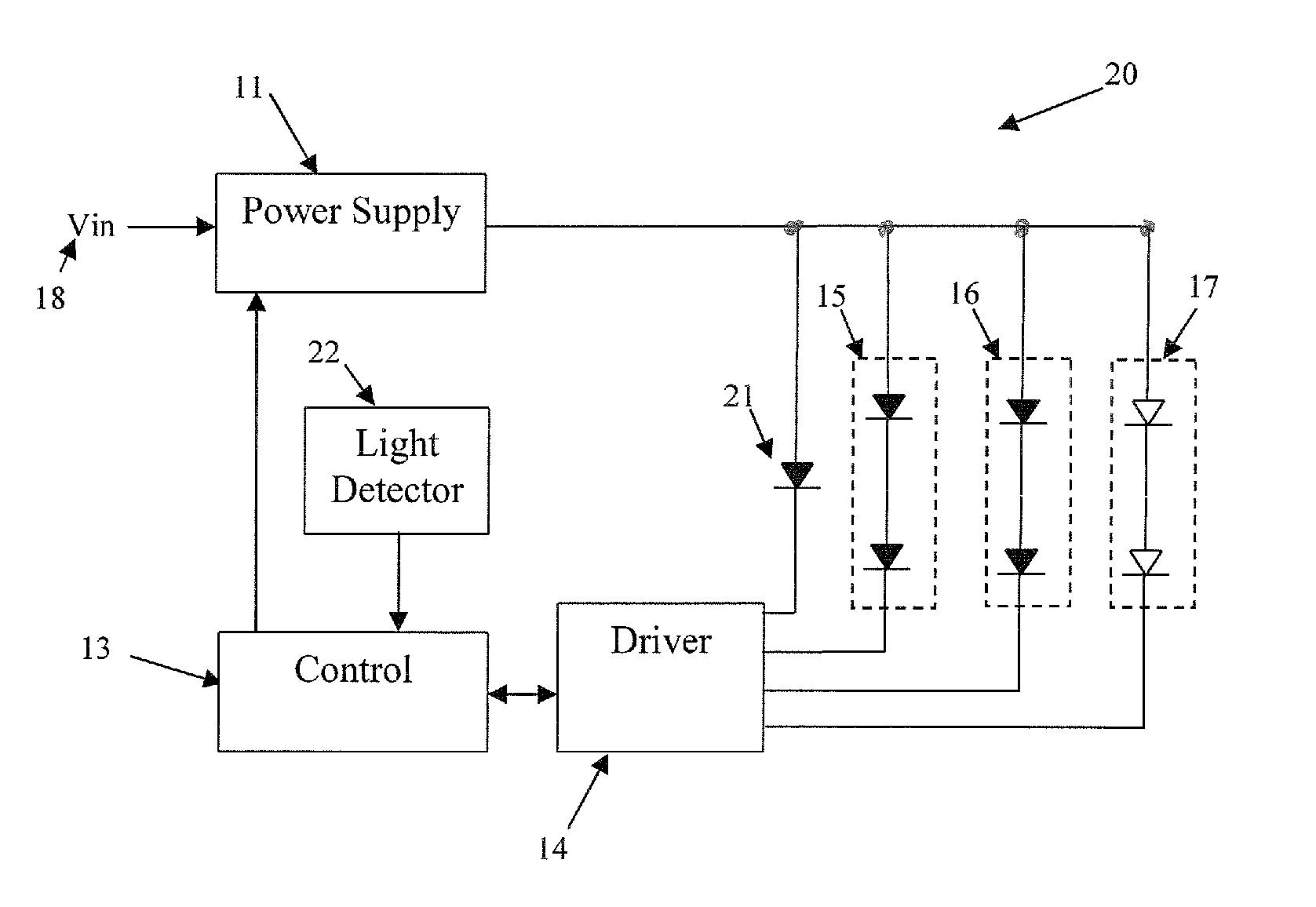
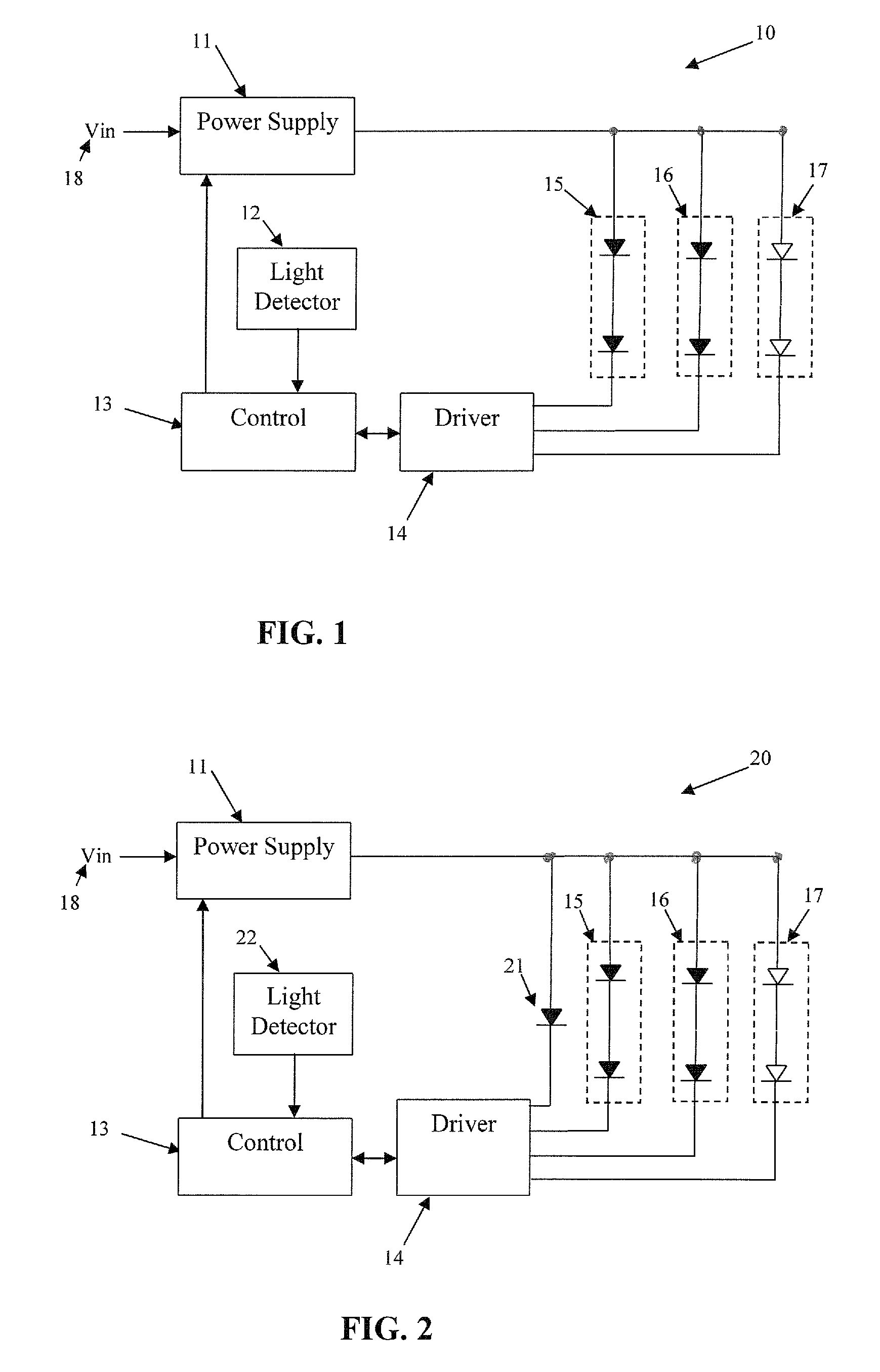
[0026]Turning now to the drawings, FIG. 1 is an example block diagram for circuitry in a conventional LED lamp 10 that includes a light detector 12 to monitor the brightness of light produced by LED chains 15, 16, and 17. Power supply 11 converts a voltage input (Vin) 18 to one or more voltages that are used to operate LED chains 15, 16, and 17, and that are also used to operat...


PUM


Abstract

An illumination device is provided having one or more illumination LEDs configured to provide illumination for the device. Along with the illumination LED is a reference LED. The illumination LED provide illumination during normal operation of the device, whereas the reference LED provides a reference illumination, but does not provide illumination during normal operation. A light detector can detect light from the illumination LED and the reference LED, and control circuitry can be used to compare light detected from the reference LED and the illumination LED to adjust a brightness for the device. The light detector can comprise a photo-detector or can comprise an LED, such as one of the illumination LEDs if more than one illumination LED is utilized. A method is also provided for controlling brightness of an illumination device.

Description

RELATED APPLICATIONS[0001]This application is related to the following co-pending applications: U.S. patent application Ser. No. 12 / 806,114 filed Aug. 5, 2010; U.S. patent application Ser. No. 12 / 806,117 filed Aug. 5, 2010; U.S. patent application Ser. No. 12 / 806,121 filed Aug. 5, 2010; U.S. patent application Ser. No. 12 / 806,118 filed Aug. 5, 2010; U.S. patent application Ser. No. 12 / 806,113 filed Aug. 5, 2010; and U.S. patent application Ser. No. 12 / 806,126 filed Aug. 5, 2010; each of which is hereby incorporated by reference in its entirety.BACKGROUND[0002]1. Field of the Invention[0003]The invention relates to the addition of an LED (light emitting diode) to an illumination device to be used as reference light source to maintain brightness over lifetime.[0004]2. Description of Related Art[0005]Lamps and displays using LEDs (light emitting diodes) for illumination are becoming increasingly popular in many different markets. LEDs provide a number of advantages over traditional lig...

Claims


Application Information

Patent Timeline
Patent Type & Authority Patents(United States)
IPC IPC(8): H05B37/02H05B44/00
CPCH05B33/0869H05B45/22
Inventor KNAPP, DAVID, J.
Owner LUTRON TECH CO LLC
Why Eureka
Try Eureka