Magnetic circuit interrupter with current limiting capability

a current limit and circuit interrupter technology, applied in the direction of circuit-breaking switches, switches with electromagnetic release, protective switch details, etc., can solve the problems of circuit breaker almost useless, circuit breaker will trip, and circuit breaker is capable of immediately tripping

Active Publication Date: 2014-06-10
CARLING TECH
View PDF18 Cites 13 Cited by
  • Summary
  • Abstract
  • Description
  • Claims
  • Application Information

AI Technical Summary

Problems solved by technology

If a power surge occurs in the electrical wiring, the breaker will trip.
The disadvantage of this device is that it is only capable of immediately tripping the circuit breaker at a single current level.
This is disadvantageous as the circuit breaker will accidentally trip on the detection of a low current spike, such as the starting of a motor.
This renders the circuit breaker almost useless as the circuit breaker will be constantly tripping when the circuit breaker does not need to be tripped.
As with Nicol above, a disadvantage of this circuit breaker is that it uses a single overcurrent coil to trip the circuit breaker and immediately trips after the detection of the second current level.
This, however, would not trip the circuit breaker in the event of a small current spike for an extended period of time, which can damage equipment connected to the circuit breaker.
Instead of setting the tripping mechanism at a high current level, many circuit breakers introduce a delay in the tripping mechanism so that the circuit breaker only trips after the detection of a current spike for a specific period of time.
The introduction of a delay, however, introduces a problem that can be very dangerous and can severely damage equipment.
For example, if a person accidentally comes into contact with a live wire or live outlet, a large current spike may occur.
Any delay in the tripping of the circuit breaker corresponds to an increase in the amount of time the person is in contact with the live wire or outlet.
This can lead to severe injury, or even death.
A short may also occur if there is a problem with the equipment connected to the circuit breaker, if the circuit breaker waits for a specific period of time to pass before tripping, the equipment connected to the circuit breaker may be severely damaged.

Method used


Image

  • Magnetic circuit interrupter with current limiting capability
  • Magnetic circuit interrupter with current limiting capability
  • Magnetic circuit interrupter with current limiting capability

Examples


Embodiment Construction

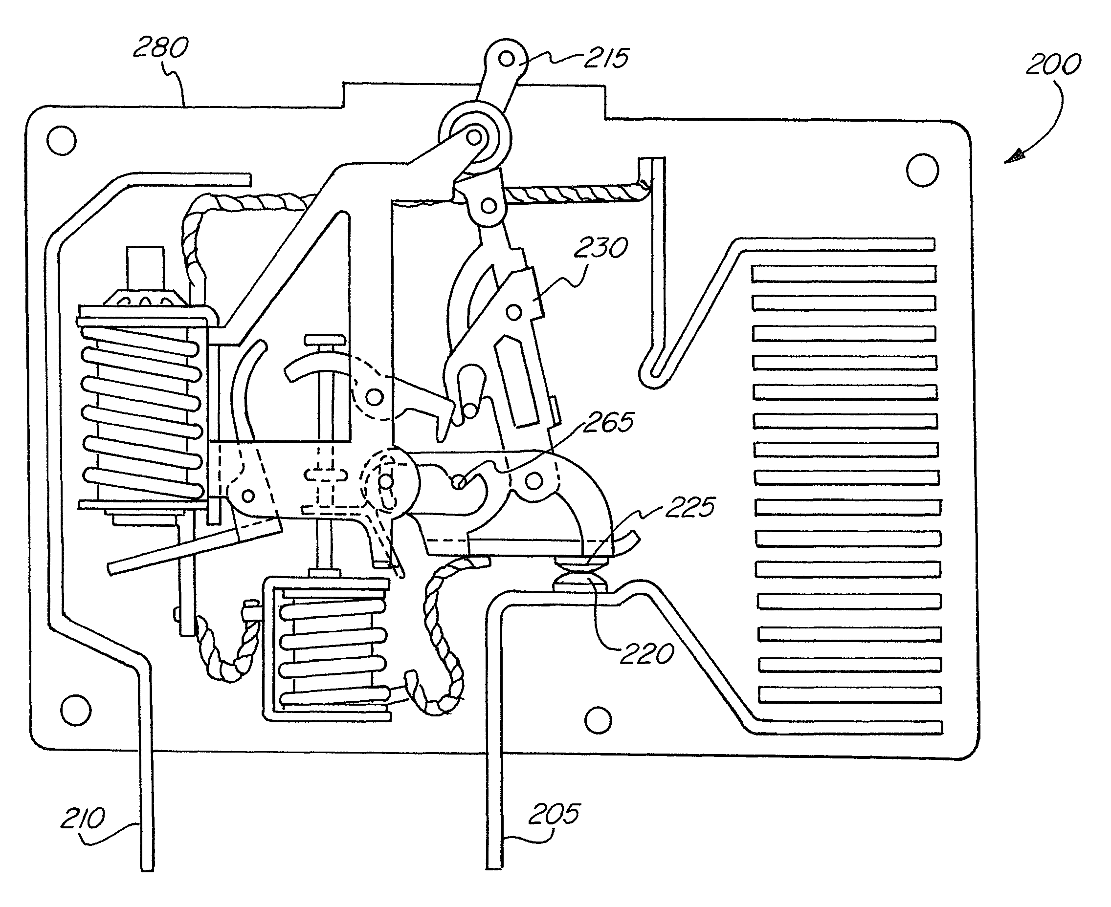
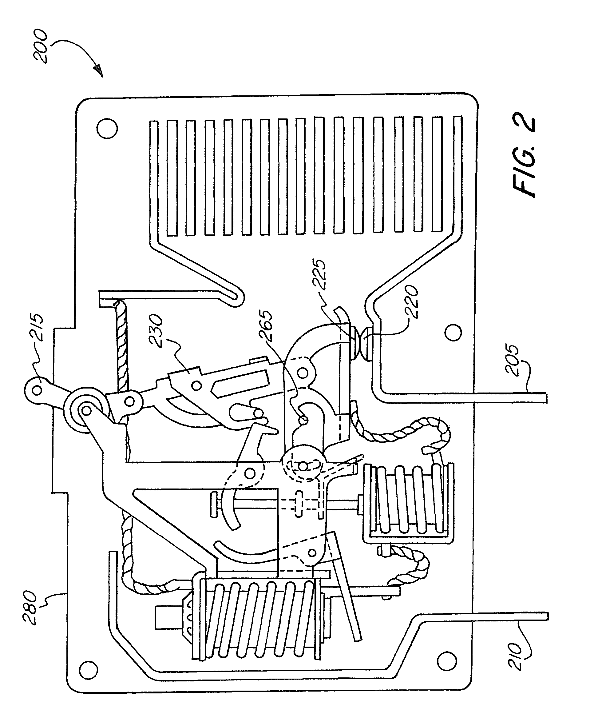
[0032]The exemplary embodiments of the present invention may be further understood with reference to the following description and the related appended drawings, wherein like elements are provided with the same reference numerals. The exemplary embodiments of the present invention are related to a device capable of opening a circuit at differing voltage or current levels and based on different durations of the voltage or current levels. Specifically, the device uses a plurality of solenoids to trip and open a circuit in a circuit interrupter. The exemplary embodiments are described with reference to a circuit breaker, but those skilled in the art will understand that the present invention may be implemented on any electrical device that has electrical contacts that can be opened and closed.

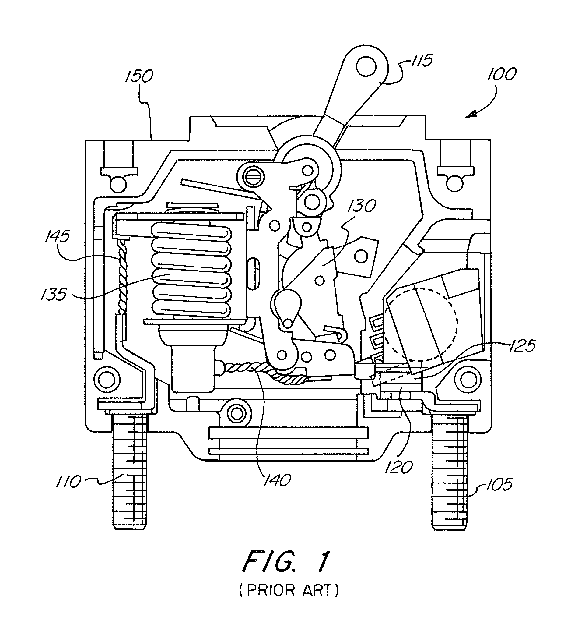
[0033]As best seen in FIG. 1, a circuit breaker 100 according to the prior art is shown. Circuit breaker 100 is a standard circuit breaker in use today. Circuit breaker 100 has a first terminal 10...


PUM


Abstract

A circuit interrupter has a first contact, a second contact, and a trip arm which moves the second contact between a closed position where the second contact is touching the first contact and an open position in which the second contact is spaced apart from the first contact. A first trip mechanism has a first solenoid, a first overcurrent sensor, and a first arm. A second trip mechanism has a second solenoid, a second overcurrent sensor, and a second arm. The first trip mechanism activates the first arm after a first threshold amount of time which actuates the trip arm when the first overcurrent sensor detects a first threshold level. The second trip mechanism activates the second arm after a second threshold amount of time which actuates the trip arm when the second overcurrent sensor detects a second threshold level, the second threshold level being different than the first.

Description

CROSS-REFERENCE TO RELATED APPLICATIONS[0001]The present application claims the benefit under 35 U.S.C. §119(e) of U.S. Provisional Patent Application Ser. No. 61 / 475,517 filed on Apr. 14, 2011, the content of which is hereby incorporated by reference.FIELD OF THE INVENTION[0002]The present invention relates generally to the protection of electrical devices, and more specifically, relates to a circuit interrupter having multiple solenoids for interrupting a circuit.BACKGROUND OF THE INVENTION[0003]A circuit interrupter is an electrical component that can break an electrical circuit, interrupting the current. A basic example of a circuit interrupter is a switch, which generally consists of two electrical contacts in one of two states; either closed meaning the contacts are touching and electricity can flow between them, or open, meaning the contacts are separated. A switch may be directly manipulated by a human as a control signal to a system, such as a computer keyboard button, or t...

Claims


Application Information

Patent Timeline
Patent Type & Authority Patents(United States)
IPC IPC(8): H01H75/10H01H81/04H01H77/06
CPCH01H71/2409H01H71/2463H01H71/44
Inventor FASANO, MICHAEL
Owner CARLING TECH
Why Eureka
Try Eureka