
System and method for controlling current limit with primary side sensing

a technology of primary-side sensing and current limit, which is applied in the direction of electric variable regulation, process and machine control, instruments, etc., can solve the problems of reducing the efficiency of the circuit, unable to perform close to the conventional primary-side sensing system, and increasing the output current to dangerous levels

Inactive Publication Date: 2005-12-06
HERCULES TECH GROWTH CAPITAL +1
View PDF33 Cites 121 Cited by
  • Summary
  • Abstract
  • Description
  • Claims
  • Application Information

AI Technical Summary

Benefits of technology

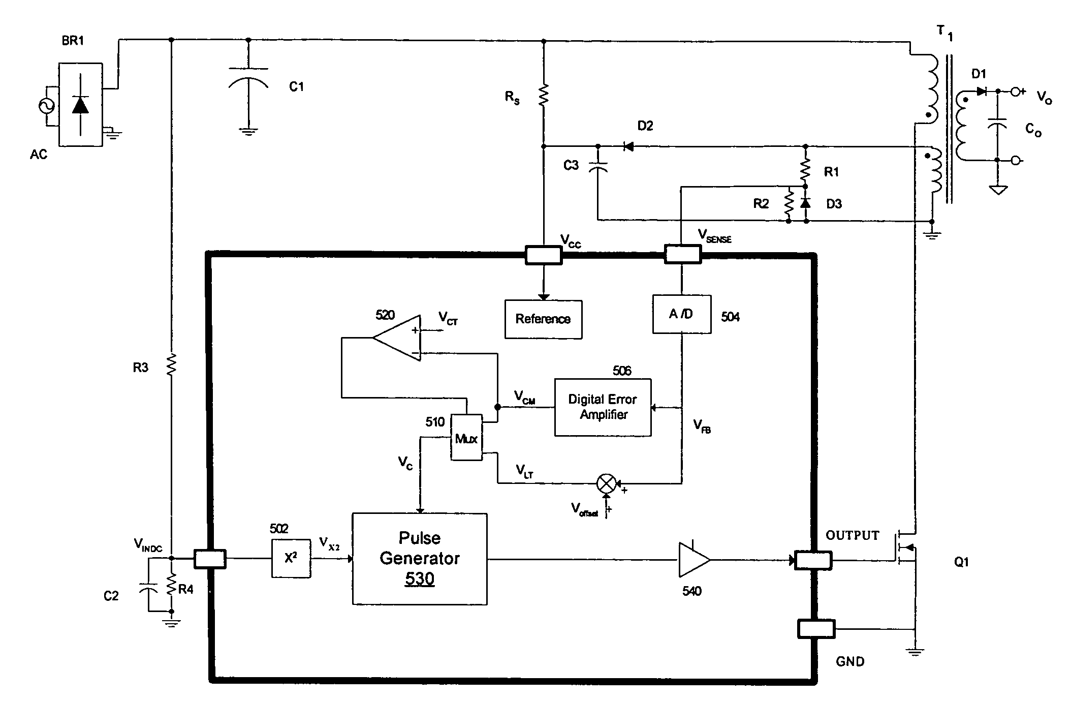
[0015]The present invention is a primary side sensing power control system and method along with a squared feed-forward signal to control the current limit such that it is maintained within a smal

Problems solved by technology

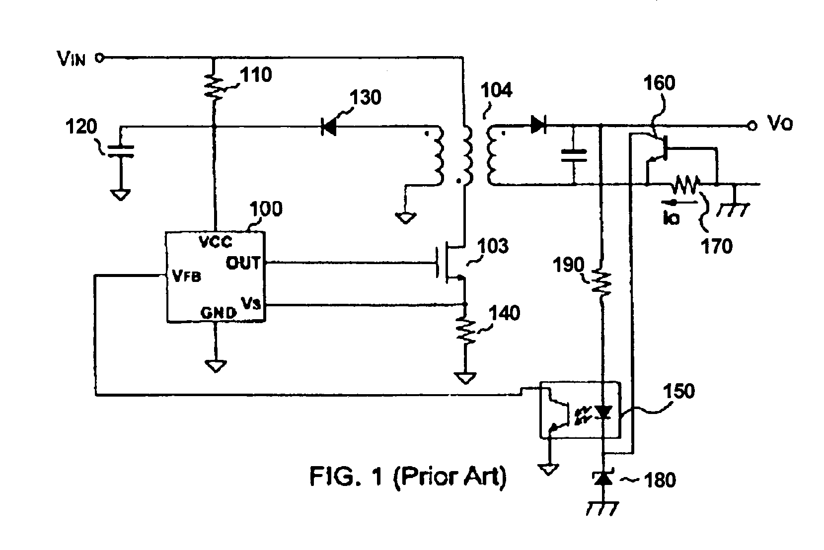
However, even in a circuit that is outputting constant power, the output current can increase to dangerous levels when the output voltage decreases.
No conventional primary-side sensing systems perform close to this ideal.
However, a problem with this type of circuit is that significant power is lost on the sense resistor 170 that decreases the efficiency of the circuit.
Such individual adjustments are time consuming and expensive.
This primary side power converter is less accurate than the secondary side sensing described above and, therefore, only provides an approximate power limit control.
Additionally, the circuit in FIG. 3 does not adequately control the output current since the circuit has insufficient information about the output voltage.

Method used


Image

  • System and method for controlling current limit with primary side sensing
  • System and method for controlling current limit with primary side sensing
  • System and method for controlling current limit with primary side sensing

Examples


Embodiment Construction

[0023]A preferred embodiment of the present invention is now described with reference to the figures where like reference numbers indicate identical or functionally similar elements. Also in the figures, the left most digits of each reference number corresponds to the figure in which the reference number is first used.

[0024]Reference in the specification to “one embodiment” or to “an embodiment” means that a particular feature, structure, or characteristic described in connection with the embodiments is included in at least one embodiment of the invention. The appearances of the phrase “in one embodiment” in various places in the specification are not necessarily all referring to the same embodiment.

[0025]The language used in the specification has been principally selected for readability and instructional purposes, and may not have been selected to delineate or circumscribe the inventive subject matter. Accordingly, the disclosure of the present invention is intended to be illustra...


PUM


Abstract

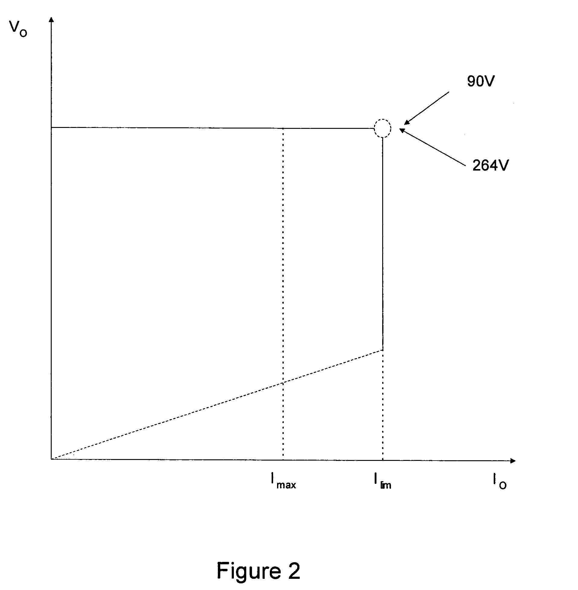
A primary side sensing power control system and method that controls the current limit such that it is maintained within a small range for any acceptable input voltages and causes the output voltage of a PWM controller to drop as the output load increases when the current limit is reached.

Description

RELATED APPLICATIONS[0001]This application is related to U.S. patent application Ser. No. 10 / 610,977 filed on Jun. 30, 2003 by Shteynberg et al., and U.S. patent application Ser. No. 10 / 735,211, filed on Dec. 12, 2003 by Eason et al. which are both incorporated by reference herein in their entirety.FIELD OF THE INVENTION[0002]The present invention relates to a power supply and more particularly to pulse width modulation (PWM) controllers for limiting current with primary-side sensing and feedback.BACKGROUND OF THE INVENTION[0003]Pulse width modulation (PWM) is a conventional technology used for controlling power converters to achieve output power regulation. Conventional flyback power converters include a power stage for delivering electrical power from a power source to a load, a switch in the power stage that electrically couples or decouples the load to the power source, and a switch controller coupled to the switch for controlling the on-time and off-time of the switch. The on-t...

Claims


Application Information

Patent Timeline
IPC IPC(8): H02M3/335
CPCH02M3/33523
Inventor SHTEYNBERG, ANATOLYZHENG, JUNJIERODRIGUEZ, HARRYTELEFUS, MARK D.ZHOU, DONGSHENG
Owner HERCULES TECH GROWTH CAPITAL
Learn More