Method and apparatus for controlling current supplied to electronic devices

a technology of electronic devices and current supply, applied in the direction of lighting and heating apparatus, process and machine control, instruments, etc., can solve the problems of high power loss of linear constant current drive circuits, unsatisfactory mode of operation, and need special power electronic devices and diligent thermal managemen

Inactive Publication Date: 2011-08-16
SIGNIFY HLDG BV
View PDF13 Cites 122 Cited by
  • Summary
  • Abstract
  • Description
  • Claims
  • Application Information

AI Technical Summary

Benefits of technology

[0013]An object of the present invention is to provide a method and apparatus for controlling current supplied to electronic devices. In accordance with one aspect of the present invention there is provided a drive and control apparatus for controlling current supplied to a string of one or more electronic devices, the apparatus comprising: a voltage converter configured to receive a first magnitude voltage from a power supply, the voltage converter configured to convert the first magnitude voltage to a second magnitude voltage in response to a control signal; a dimming control means configured to receive the second magnitude voltage and a dimming control signal, the dimming control means configured to control transmission of the second magnitude voltage to the string based on the dimming control signal, the dimming control means configured for multi-mode operation, wherein the dimming control signal is indicative of a desired mode of operation of the dimming control means; a current sensing means in series with the string and configured to generate a feedback signal indicative of current flowing through the string; and a feedback means electrically coupled to the voltage converter and current sensing means, the feedback means configured to receive the feedback signal and generate the control signal based on the feedback signal, the feedback means further configured to provide the control signal to the voltage converter.

Problems solved by technology

When the drive current of a series connection of LEDs is reduced below a certain limit, some LEDs can completely stop emitting light before others do which can result in an undesired mode of operation.
However, many linear constant current drive circuits incur high power losses and require special power electronic devices and diligent thermal management.
This drive circuit has high power losses due to the biasing resistors and the biasing resistors can require costly calibration to provide accurate current control.
This closed loop circuit however, does not enable full range current pulse duty factor control.
This method however, uses PWM switching frequencies of 20 Hz to 20 kHz which generate audible noise and can detrimentally affect the LEDs by thermally cycling the LED dies which consequently reduces reliability and lifetime of the devices.
This method however, can only be applied to fly-back and push-pull type voltage converters and cannot control the LED drive current directly.
This method does not significantly reduce drive circuit power loss or improve overall system efficiency.
In addition, this method typically only works within desired parameters up to drive frequencies of the order of 400 Hz and does not allow for high frequency switching.
Consequently, a drive circuit according to this method can generate undesirable audible noise and may impose excessive thermal stress on the connected LED arrays.
This method incorporates essential elements of a standard Buck converter design, however it is not able to control parallel LED strings which require different forward voltages.
This method discloses how to use high-side transistor switches as variable resistors to limit the current per LED string, however high-side transistor switches can induce large power losses and decrease the overall efficiency of the drive circuit.
However, this solution does not provide for dimming, a switching capability of the load, or a means for controlling the peak load current for instances where the voltage converter is switched.
This approach can result in lower overall system efficiency.
This inefficiency may worsen at switching frequencies higher than a few hundred Hertz, as there is no provision for maintaining the voltage set point during the OFF period and therefore the internal current limiting circuitry would need to be active over most duty cycles.
In addition this control chip does not allow for efficient drive of LEDs with a wide range of forward voltages, but typically requires to be tuned for each LED or string thereof by means of external resistors.
For example, when this procedure is used for the activation of LEDs, the light output of the LED during the transition periods, for example rise and fall times, may not be at the desired level and therefore may result in variations in the light output, which may be readily apparent during low duty cycles, for example.

Method used


Image

  • Method and apparatus for controlling current supplied to electronic devices
  • Method and apparatus for controlling current supplied to electronic devices
  • Method and apparatus for controlling current supplied to electronic devices

Examples


Embodiment Construction

Definitions

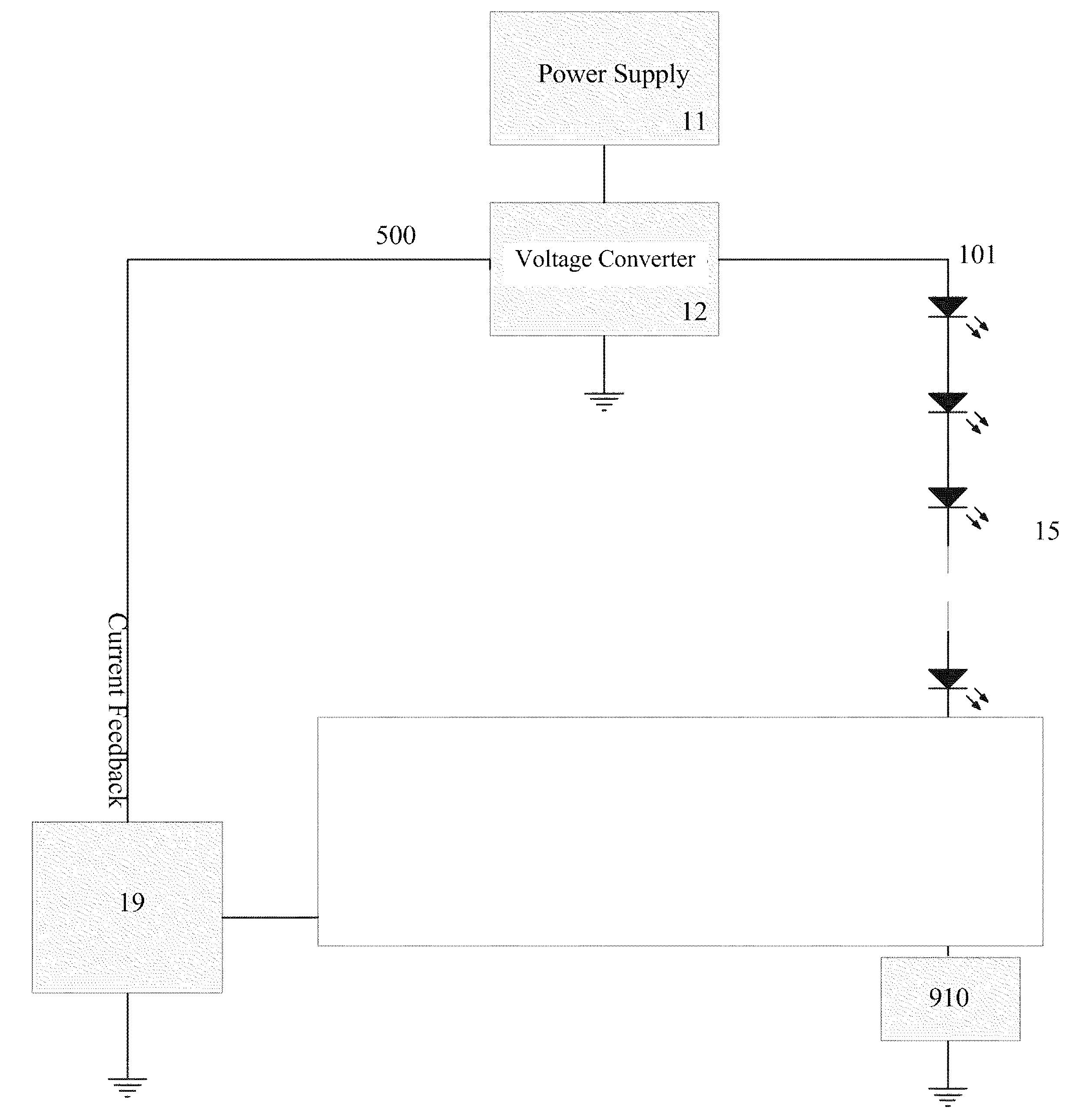
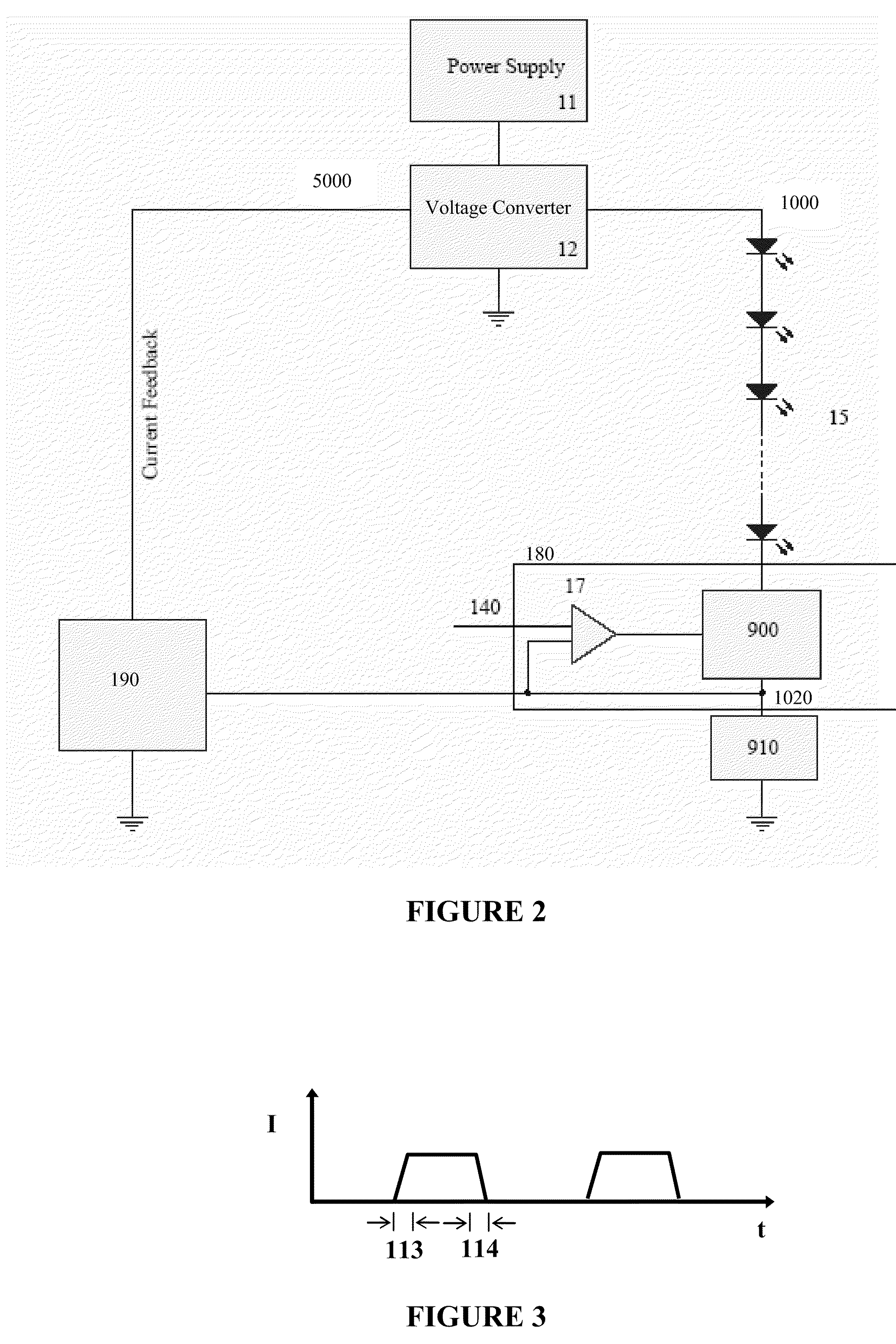
[0037]The term “power supply” is used to define a system comprising an input and an output for transforming a first form of electricity provided at the input, conditioning the first form of electricity into a second form of electricity, and providing the second form of electricity at the output. A power supply can accept a predetermined range of forms of electricity at the input and can condition the electricity into and provide a predetermined range of forms of electricity at the output.

[0038]The term “voltage converter” is used to define a system comprising an input and an output that can convert an input voltage of a first magnitude into an output voltage of a second magnitude, wherein the first and the second magnitude can be the same or different.

[0039]The term “electronic device” is used to define any apparatus whose level of operation is dependent on the form of supplied electricity. Examples of electronic devices include light-emitting elements, servo motors, and ...


PUM


Abstract

The present invention provides a drive and control apparatus provides a desired switched current to a load including a string of one or more electronic devices. A voltage conversion means, based on an input control signal converts the magnitude of the voltage from the power supply to another magnitude that is desired at the high side of the load. A dimming control means provides control for activation and deactivation of the load and may further provide a means for current limiting. A feedback means is coupled to the voltage conversion means and a current sensing means and provides a control signal to the voltage conversion means that is indicative of voltage drop across the current sensing means which represents the current flowing through the load. Based on the control signal received, the voltage conversion means can subsequently adjust its output voltage such that a constant switched current is provided to the load.

Description

FIELD OF THE INVENTION[0001]The present invention pertains to the field of control of electronic devices, and in particular to a method and apparatus for switched drive current control of electronic devices.BACKGROUND[0002]Recent advances in the development of semiconductor light-emitting diodes (LEDs) and organic light-emitting diodes (OLEDs) have made these devices suitable for use in general illumination applications, including architectural, entertainment, and roadway lighting, for example. As such, these devices are becoming increasingly competitive with incandescent, fluorescent, and high-intensity gas discharge lamps.[0003]The amount of light emitted by an LED under operating conditions directly depends on the electronic current that flows through the device. Because of variations in device characteristics, the same device current can lead to perceivable different luminous flux output under certain operating conditions even when the LEDs are of the same kind. When the drive c...

Claims


Application Information

Patent Timeline
Patent Type & Authority Patents(United States)
IPC IPC(8): H05B41/16H05B44/00
CPCH05B33/0851H05B33/0827H05B45/46H05B45/37Y02B20/30H05B45/10
Inventor JURNGWIRTH, PAULROBINSON, SHANE P.MATZA, CRAIG
Owner SIGNIFY HLDG BV
Why Eureka
Try Eureka