Solid state LED bridge rectifier light engine

a technology of led bridge rectifier and solid state light, which is applied in the direction of electroluminescent light source, electric lighting source, and use of semiconductor lamps to speed up light pulsation, and achieve the effects of shortening or shortening the time duration, speeding up the light pulsation, and prolonging or shortening the persisten

Inactive Publication Date: 2007-03-29
LIGHTING SCI GROUP
View PDF13 Cites 134 Cited by
  • Summary
  • Abstract
  • Description
  • Claims
  • Application Information

AI Technical Summary

Benefits of technology

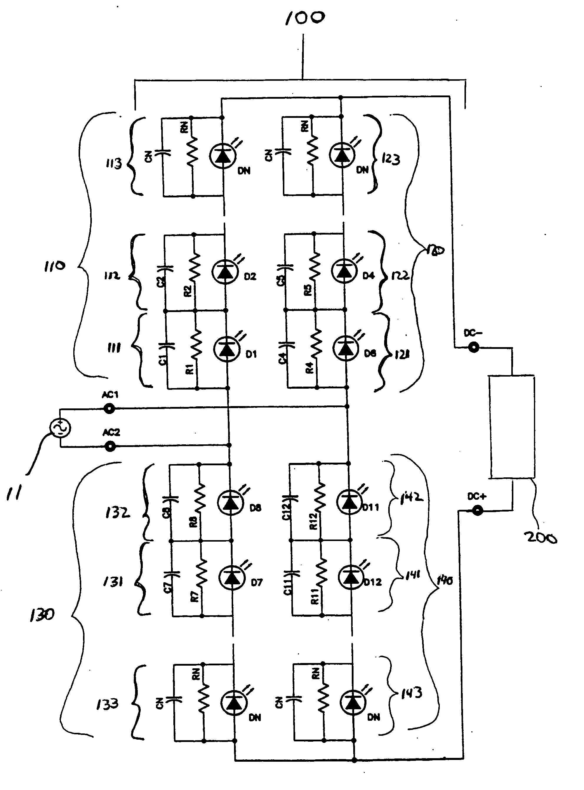
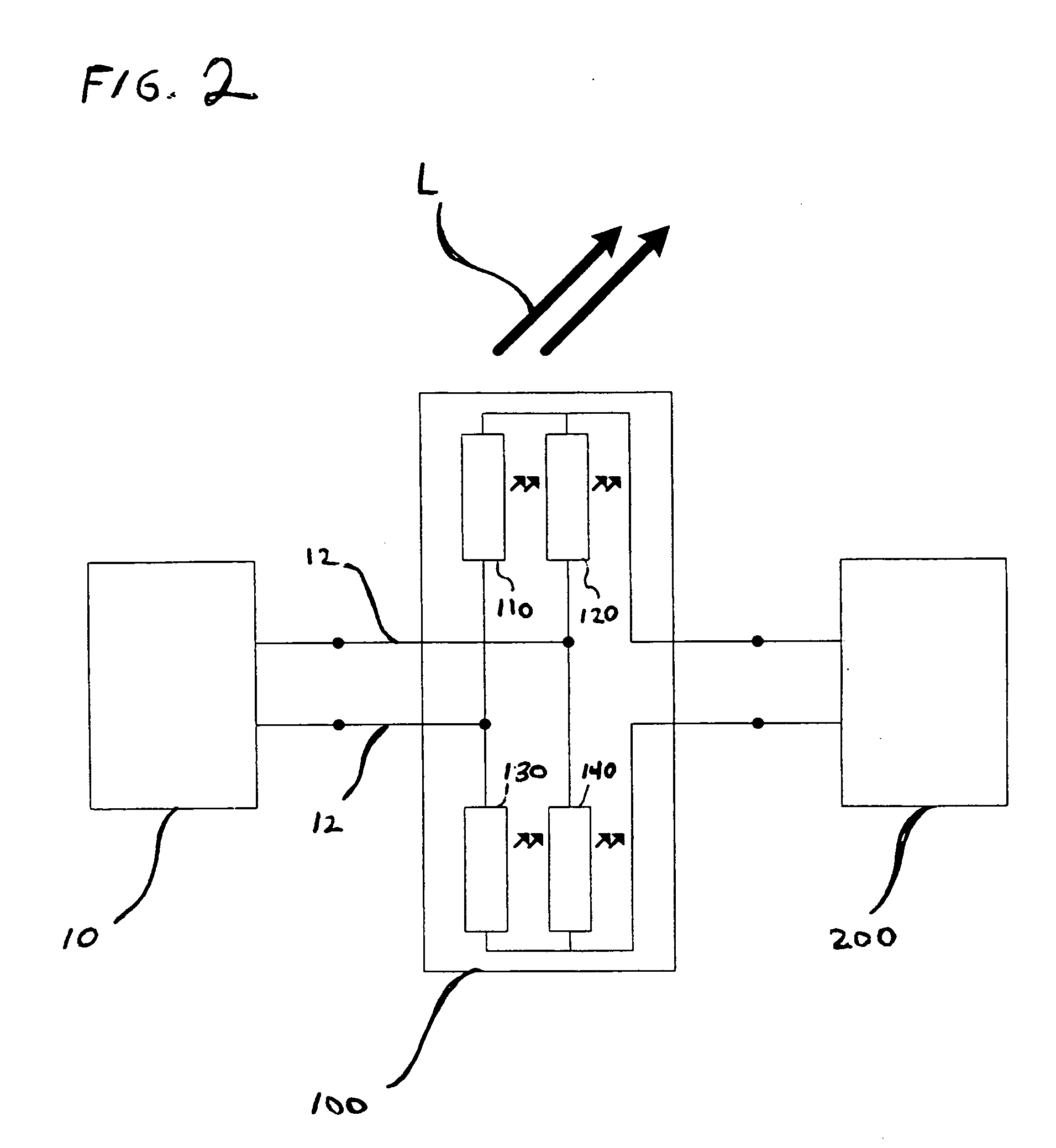
[0012] The turn-on and turn-off time for typical LEDs is in the tens to one hundred nanosecond range. With this response time, LEDs will virtually follow the low frequency AC waveform without delay. According to an aspect of an embodiment of the invention, through rectification, the light pulsation or ripple frequency will typically be increased to approximately twice the frequency of the input AC line current (e.g., 100 to 120 Hz). This frequency doubling has the advantageous effect of speeding up the light pulsation to a frequency beyond what is typically perceptible to human observers, thus making it more appealing for use in standard lighting applications than would an LED array powered directly from AC current that was not configured into a bridge rectifier. In addition, the frequency doubling that occurs in the LED bridge rectifier configuration results in a shortening of the time duration between current peaks to about 10 ms for a 50 Hz line and about 8 ms for a 60 Hz line. The shortened peak to peak period, together with the advantageous use of phosphors having a persistence of 5 to 10 times that duration, masks the light pulsation or flicker, allowing it to be smoothed and integrated into a nearly continuous white light output. Phosphors having a longer or shorter persistence may also be used advantageously.
[0013] The light engine arrangement according to certain embodiments of the invention can be used as a solid-state replacement for conventional Edison-base incandescent lamps or as a replacement for low-voltage halogen lamps or other low voltage lamps. Advantageously, since no additional electronic components need be inserted into the power path, the increased useful life offered by the solid state light engine need not be compromised.

Problems solved by technology

Although full-wave bridge rectifiers are known in the art, they utilize non-light emitting diodes, and are used to convert AC current to DC current for use as a power source for external electronic components, not to produce useful illumination.

Method used


Image

  • Solid state LED bridge rectifier light engine
  • Solid state LED bridge rectifier light engine
  • Solid state LED bridge rectifier light engine

Examples


Embodiment Construction

[0028] Embodiments of the invention are directed to a solid state light engine producing white or near white light that is constructed by using LEDs that emit blue or ultraviolet wavelength emission which stimulates a phosphor, or some mixture of phosphors, that emit light in the green, yellow and / or red wavelengths. The combination of all these wavelengths is perceived as white light by the human eye. If one were to look at just a monochrome color LED driven with an AC source, one would see the pulsation of the light at the 50 Hz or 60 Hz frequencies. Even if the pulsation is above the detectable threshold to 100 Hz or 120 Hz, the pulsation can still be detected when the light interacts with objects or images moving or pulsating at close to the LED pulse rate or harmonics of that rate. This is, at the least, annoying and, at worst, potentially dangerous. Strobing light could possibly make moving or spinning objects appear to be not moving at all. An example of this is a fluorescent...


PUM


Abstract

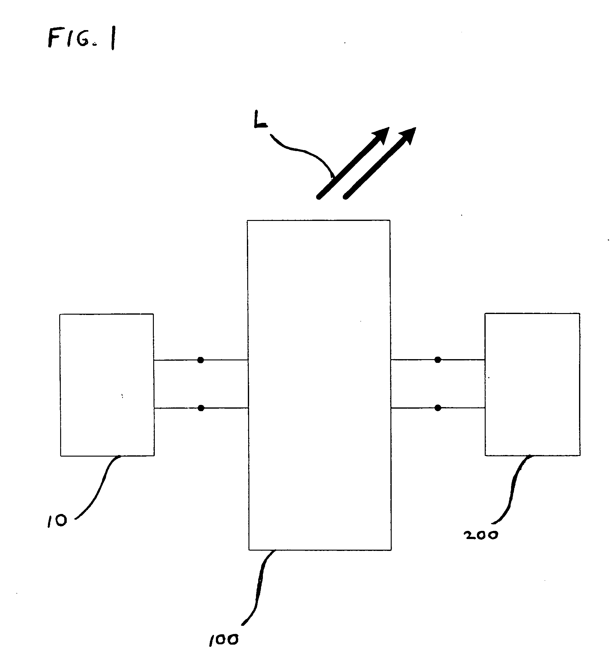
A solid-state light engine comprised of light emitting diodes (LEDs) configured into a bridge rectifier with a current limiting module coupled to the LED bridge rectifier. The light engine may be packaged for high temperature operation. Optionally, the LEDs comprise wavelength-converting phosphors with a persistence that is a multiple of the peak to peak current period, to smooth and mask ripple frequency pulsation of emitted light.

Description

CROSS-REFERENCE TO RELATED APPLICATION [0001] This application claims the benefit of U.S. Provisional Patent Application No. 60 / 685,680, filed May 27, 2005, the entire disclosure of which is hereby incorporated by reference herein.BACKGROUND OF THE INVENTION [0002] 1. Field of the Invention [0003] Embodiments of the invention relate to a solid-state light engine that is directly compatible with alternating current (AC) input power, without the need for a separate rectification module, but that can also alternatively be powered by direct current (DC) input power. [0004] 2. Related Art [0005] In many lighting applications, solid-state light engines are superior to conventional incandescent lamps. Beneficially, solid-state light engines can, in certain circumstances, achieve an almost 20% improvement in efficiency and an extended lifetime (e.g. exceeding 50,000 hours) as compared to incandescent lamps. [0006] Traditional solid-state light engines are powered by a direct current or puls...

Claims


Application Information

Patent Timeline
Patent Type & Authority Applications(United States)
IPC IPC(8): H05B39/00
CPCH05B33/0803H05B33/0809H05B33/0821Y02B20/348H01L33/56H01L2924/0002Y02B20/342H01L2924/00H05B45/40H05B45/37Y02B20/30
Inventor BURDALSKI, ROBERT J.MAZZOCHETTE, JOSEPH B.
Owner LIGHTING SCI GROUP
Why Eureka
Try Eureka