Image generation apparatus

a technology of image generation and composite images, which is applied in the direction of television systems, instruments, transportation and packaging, etc., can solve the problems of difficult for the driver to understand the clearance between the vehicle body and the obstacle, the inability of the auxiliary light source, etc., to illuminate the entire region, and the inability to display the subject image in the composite image with enough brightness, etc., to achieve the effect of improving the visibility of the subject image to be shown in the composite image, reducing the number of user

Active Publication Date: 2014-06-10
FUJITSU GENERAL LTD
View PDF19 Cites 4 Cited by
  • Summary
  • Abstract
  • Description
  • Claims
  • Application Information

AI Technical Summary

Benefits of technology

[0011]In the case where the lighting system emits the auxiliary light, the image generation apparatus makes the image display range smaller than the image display range in the case where the lighting system does not emit the auxiliary light. Accordingly, a region not illuminated by the lighting system is reduced in the image display range. As a result, the number of times when the user has to watch the subject image having poor visibility can be reduced.
[0013]A range which is bright enough to identify the subject image can be set as the image display range. Accordingly, visibility of the subject image to be shown in the composite image can be improved.
[0015]In the case where the lighting system emits the auxiliary light, the subject image shown in the composite image is made larger than that in the case where the lighting system does not emit the auxiliary light. Accordingly, visibility of the subject image to be shown in the composite image can be improved.
[0016]Therefore, the object of the invention is to reduce the number of times when a user has to watch the subject image which has poor visibility.

Problems solved by technology

Therefore, it is difficult for the driver to understand a clearance between the vehicle body and an obstacle.
In a dark surrounding environment, such as at night, there is a case where the images of the surroundings of the vehicle cannot be displayed with enough brightness because light exposure is insufficient for such an image display system to shoot images.
However, since capabilities of the auxiliary light source installed on the vehicle is limited, it is difficult for the auxiliary light source, etc. to illuminate the entire region that can be displayed.
The visibility of a subject image of an object is extremely poor in such a dark region, compared to a subject image of an object in a region illuminated.

Method used


Image

  • Image generation apparatus
  • Image generation apparatus
  • Image generation apparatus

Examples


first embodiment

[0032]

[0033]

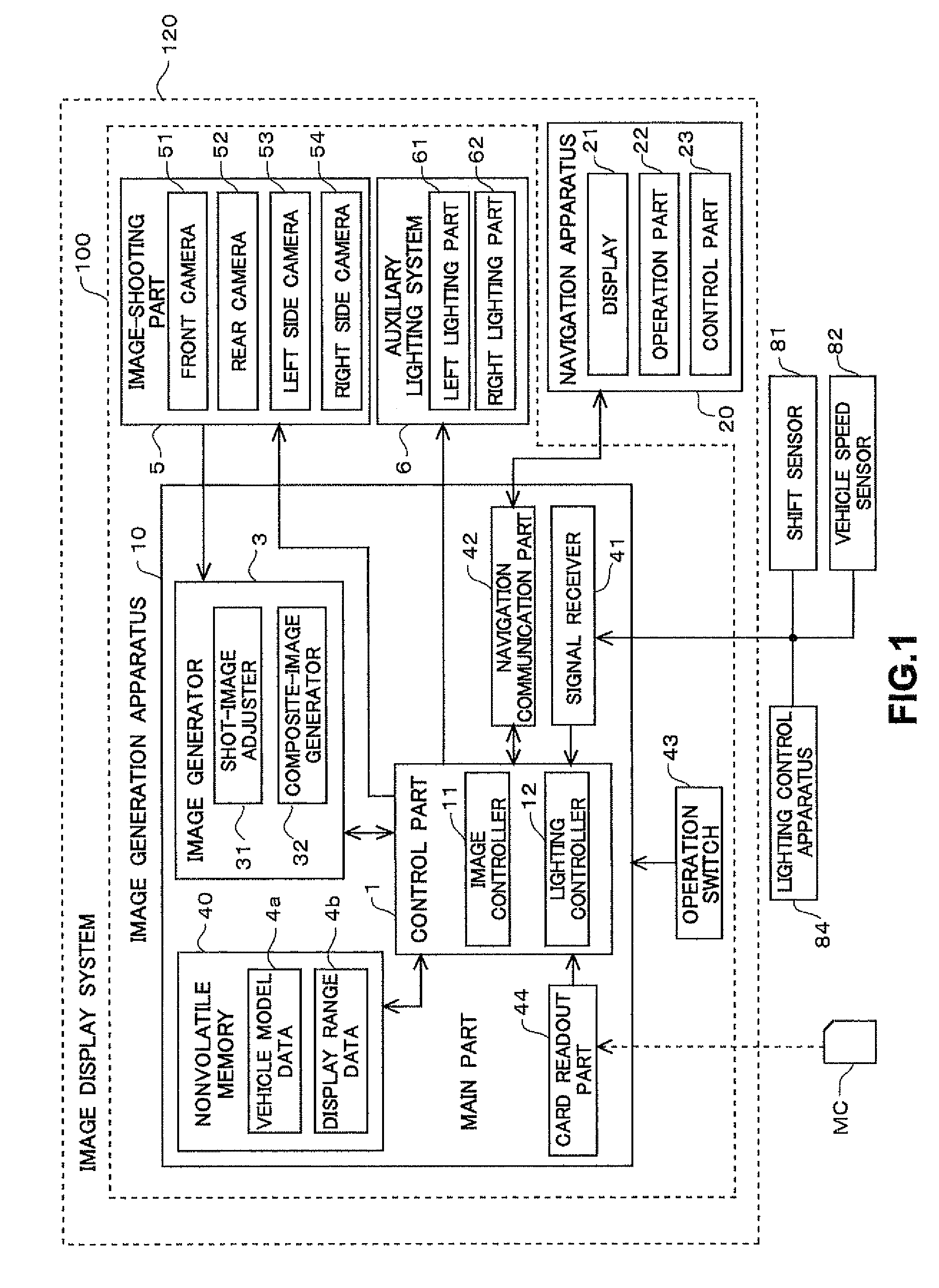
[0034]FIG. 1 shows a block diagram showing a configuration of an image display system 120 that is a first embodiment of this invention. The image display system 120 is for installation in a vehicle (a car in this embodiment) and has functions for generating an image by shooting surroundings of the vehicle and of displaying the image generated in a cabin of the vehicle. The image display system 120 allows a user of the image display system 120 (mainly a driver) to recognize a situation around the vehicle in substantially real time.

[0035]As shown in FIG. 1, the image display system 120 mainly includes an image generation apparatus 100 that generates an image showing the surroundings of the vehicle, and a navigation apparatus 20 that displays a variety of information for the user in the vehicle. The image generated by the image generation apparatus 100 is displayed on the navigation apparatus 20.

[0036]The navigation apparatus 20 provides navigation guidance for the user. Th...

second embodiment

[0106]

[0107]Next, a second embodiment is explained. The image display system of the second embodiment is almost the same in the structure and the procedure as the first embodiment, but is partly different from the first embodiment. Therefore, differences from the first embodiment are mainly explained hereinbelow. In the first embodiment, both the left lighting part 61 and the right lighting part 62 emit light approximately simultaneously. However, in the second embodiment, it is possible to switch to an illuminating state where only a left lighting part 61 is emitting light. A press of an operation switch 43 can switch between an illuminating state where both the left lighting part 61 and a right lighting part 62 are emitting light and the illuminating state where only the left lighting part 61 is emitting light (hereinafter referred to as “a left lighting part 61-illuminating state”).

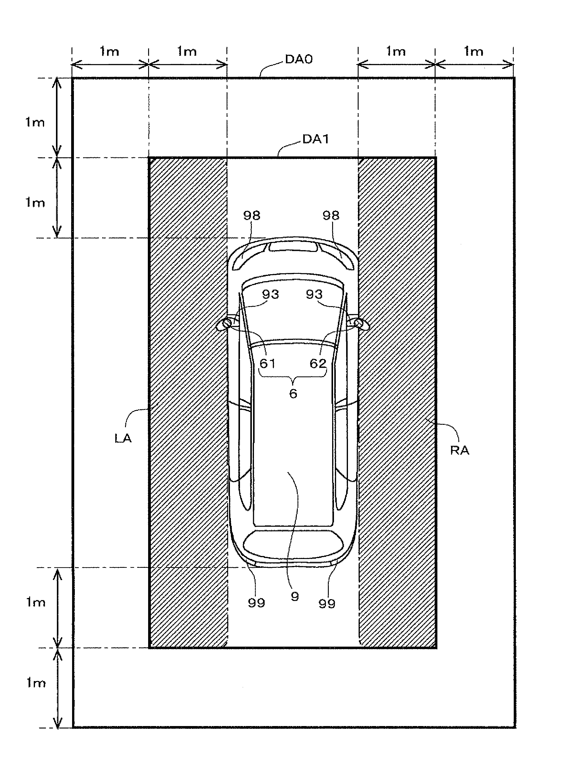
[0108]FIG. 9 shows a region around a vehicle 9 that can be illuminated by the left lighting part 61...

modification example

[0115]

[0116]Hereinbefore, the embodiments of this invention have been described. However, this invention is not limited to the aforementioned embodiments, but various modifications are possible. Hereinbelow, such modifications will be explained. Each of all embodiments including the embodiments described above and below can be arbitrarily combined with one or more of the others.

[0117]In the aforementioned embodiments, in the case where the auxiliary lighting system 6 emits light, the subject image in the composite image is made greater than that in the case where the auxiliary lighting system 6 does not emit light. On the other hand, as shown in FIG. 11, a size of the subject image in a composite image CP1 in a state where the auxiliary lighting system 6 does not emit light (an upper section of FIG. 11) may be the same as a size of a subject image in a composite image CP4 in a state where the auxiliary lighting system 6 emits light (a lower section of FIG. 11).

[0118]In the aforement...


PUM


Abstract

An image display system makes a range of a region around a vehicle to be shown in a composite image as a subject image in a case where an auxiliary lighting system emits auxiliary light, smaller than that in a case where the auxiliary lighting system does not emit auxiliary light. As a result, an image display system can reduce the number of times when a user has to watch the subject image of an object in a region not illuminated by the auxiliary lighting system.

Description

BACKGROUND OF THE INVENTION[0001]1. Field of the Invention[0002]The invention relates to a technology that generates images to be displayed on a display apparatus installed in a vehicle.[0003]2. Description of the Background Art[0004]A conventionally-known image display system is of a type for installation in a vehicle, such as a car, to display images of the surroundings of the vehicle shot with a camera mounted on the vehicle, on an in-vehicle display. By using the image display system, a driver can understand the situation around the vehicle in substantially real time.[0005]For example, a region outside a front fender of the vehicle, which is an opposite side to a driver seat, is often a blind spot for a driver. Therefore, it is difficult for the driver to understand a clearance between the vehicle body and an obstacle. On the other hand, when the image display system is used, an on-vehicle camera shoots images showing the region outside the front fender and the images are displa...

Claims


Application Information

Patent Timeline
Patent Type & Authority Patents(United States)
IPC IPC(8): H04N7/18B60Q1/00G03B15/05
CPCG03B15/02B60Q1/04B60Q1/26G03B37/04B60Q1/2665B60Q9/005
Inventor YAMADA, MASAHIROMATSUOKA, AZUSATANIGUCHI, SUSUMU
Owner FUJITSU GENERAL LTD
Why Eureka
Try Eureka