
Electrical arrangement of hybrid ignition device

a hybrid ignition and electric arrangement technology, applied in the direction of corona discharge, lighting and heating apparatus, instruments, etc., can solve the problems of arc discharge, inability to provide reliable ignition, and all the stored energy of the system is immediately discharged and depleted, and achieves reliable ignition. , the effect of reliable ignition

Active Publication Date: 2014-06-10
FEDERAL MOGUL IGNITION
View PDF19 Cites 1 Cited by
  • Summary
  • Abstract
  • Description
  • Claims
  • Application Information

AI Technical Summary

Benefits of technology

[0010]Instead of decreasing the energy provided to the electrode at the onset of arc discharge, as in systems of the prior art, the system and method of the present invention includes providing energy stored in an auxiliary energy circuit to the electrode to intentionally maintain the arc discharge and ensure a robust and reliable ignition.

Problems solved by technology

However, if the voltages increases beyond a certain threshold, the increasing ion concentration results in a cascading process typically causing the corona discharge to transform into an arc discharge.
In typically corona ignition systems, when arc discharge occurs, all of the stored energy of the system is immediately discharged and depleted.
The arc discharge may be of short duration and thus not capable of providing reliable ignition.
In addition, other situations or engine conditions can cause arc discharge.
The arc discharge may also occur when the igniter is fouled by fuel of carbon deposits, or when the piston is too close to the igniter, or during other situations where there is low electrical resistance between the electrode and ground.
The arc discharge is typically unintentionally formed and undesirable, but there are certain situations where arc discharge is intentionally formed.
However, reducing the voltage is oftentimes not practical or not effective in returning to corona discharge and providing reliable ignition.

Method used


Image

  • Electrical arrangement of hybrid ignition device
  • Electrical arrangement of hybrid ignition device
  • Electrical arrangement of hybrid ignition device

Examples


Embodiment Construction

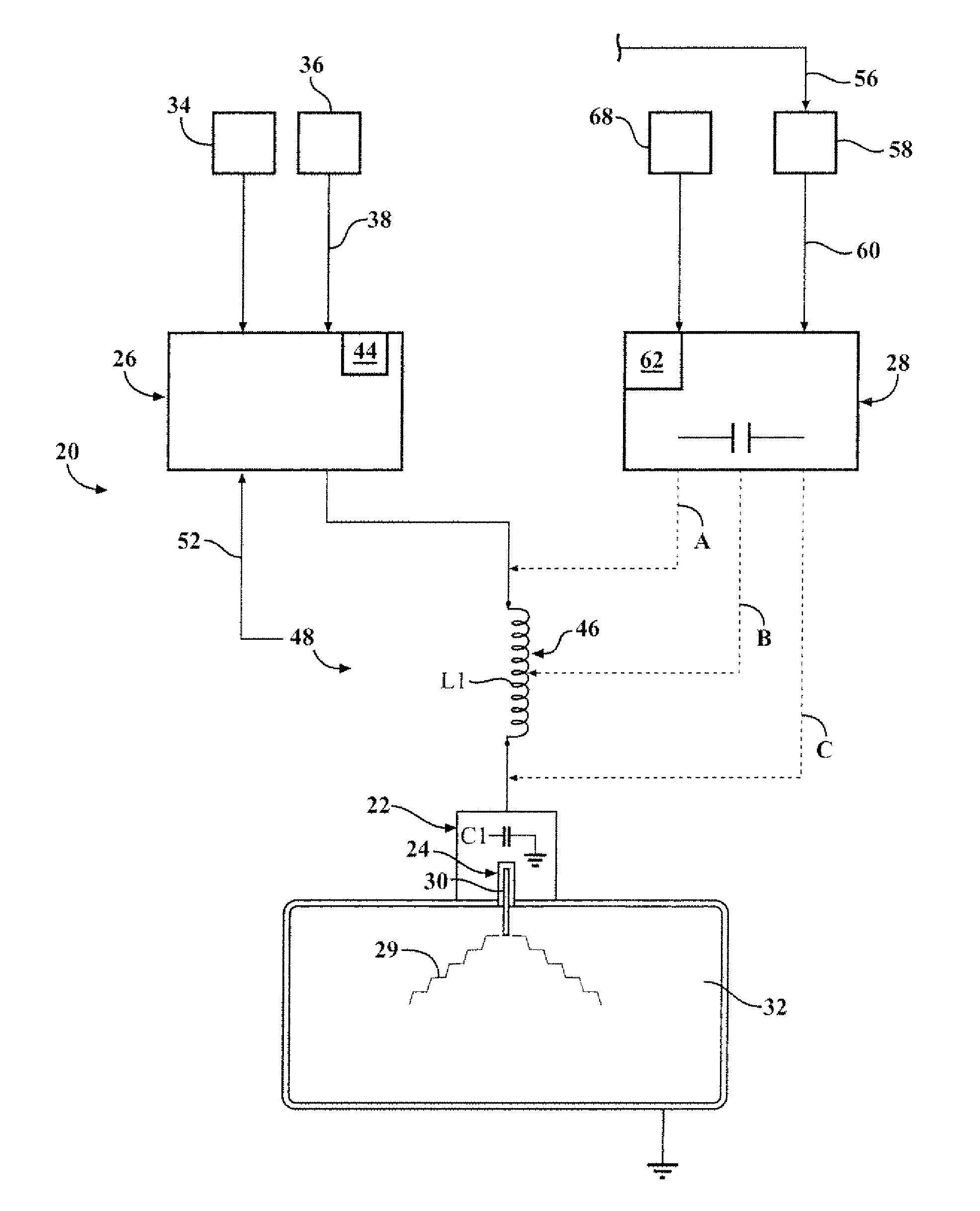
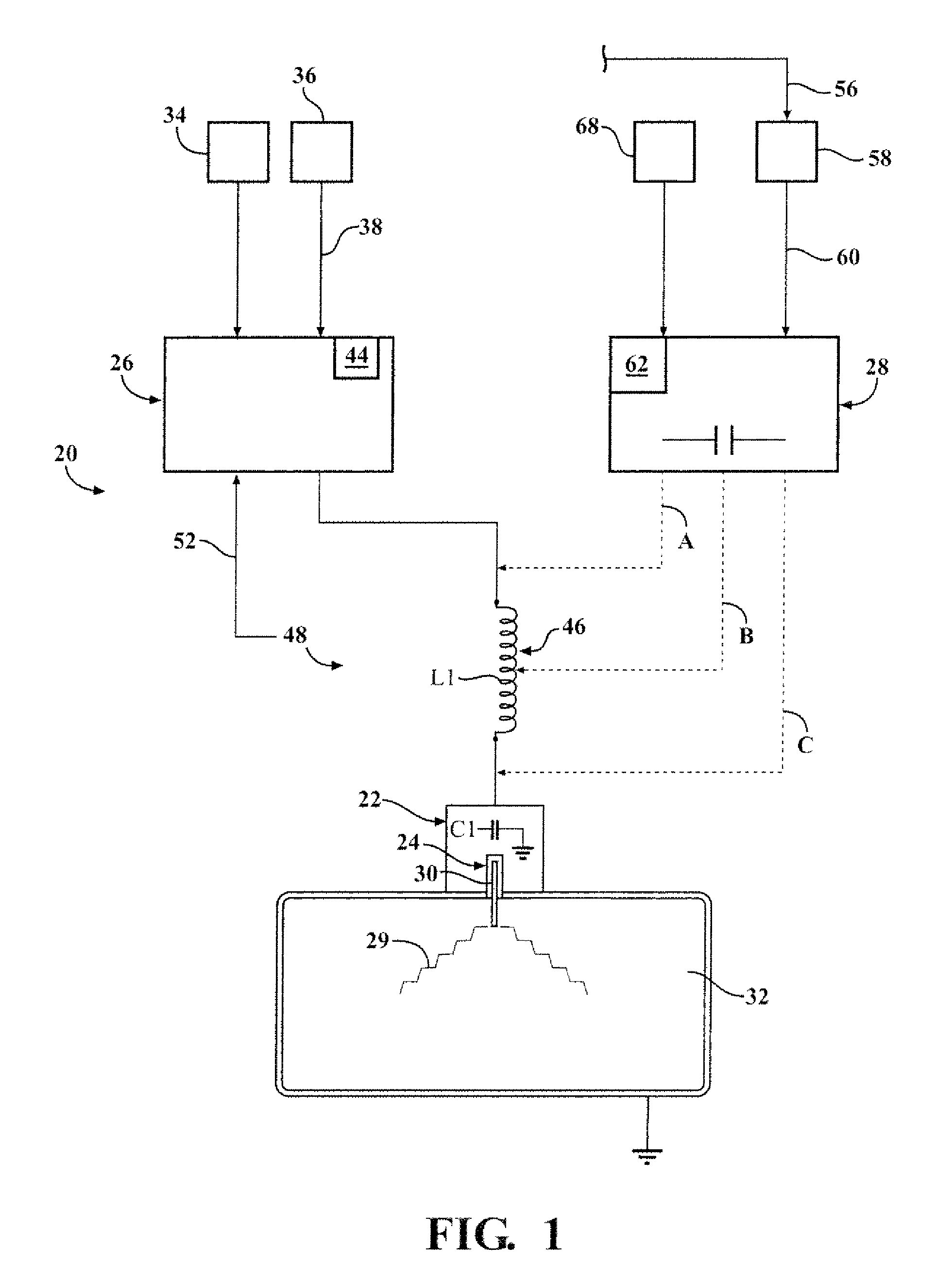
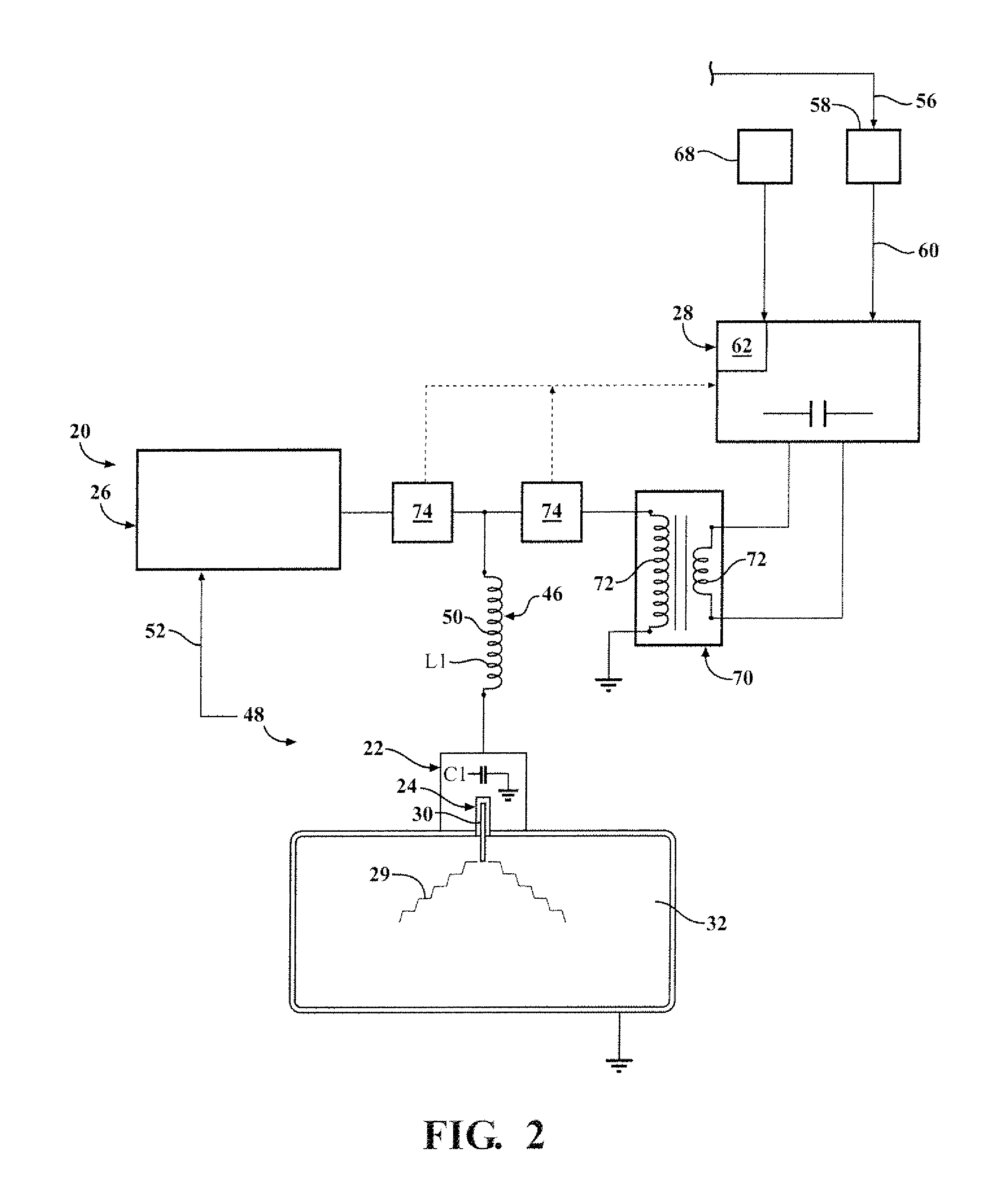
[0016]One aspect of the invention provides a corona ignition system 20 for igniting a mixture of fuel and air of a combustion chamber 32 comprising a firing end assembly 22, a corona drive circuit 26, and an energy storage and delivery circuit, referred to as an energy circuit 28. The firing end assembly 22 comprises an igniter 24 including an electrode 30 projecting into a combustion chamber 32. The corona drive circuit 26 transmits energy to the electrode 30 in an amount capable of emitting an electrical discharge, typically corona discharge but maybe arc discharge, from the electrode 30. The energy circuit 28 is auxiliary to the corona drive circuit 26 and stores supplemental energy while the corona drive circuit 26 transmits energy to the electrode 30. When arc discharge is detected, the energy circuit 28 then transmits the stored energy to the electrode 30 to intentionally maintain the arc discharge 29. The stored energy transmitted to the electrode 30 provides a robust arc dis...


PUM


Abstract

A corona ignition system 20 includes a corona drive circuit 26 and an auxiliary energy circuit 28. The energy circuit 28 stores energy during a standard corona ignition cycle. When arc discharge occurs or corona discharge switches to an arc discharge, the energy circuit 28 discharges the stored energy to the electrode 30 to intentionally maintain a robust arc discharge 29 and thus provide reliable ignition. The stored energy is transmitted to the electrode 30 over a predetermined period of time. The arc discharge is detected and an arc control signal 60 is transmitted to the energy circuit 28, triggering discharge of the stored energy to the electrode 30. The stored energy can be transmitted to the electrode 30 along a variety of different paths. The voltage of the stored energy is typically increased by an energy transformer 70 before being transmitted to the electrode 30.

Description

CROSS REFERENCE TO RELATED APPLICATION[0001]This application claims the benefit of application Ser. No. 61 / 378,673 filed Aug. 31, 2010.BACKGROUND OF THE INVENTION[0002]1. Field of the Invention[0003]This invention relates generally to a corona ignition system and method for igniting a mixture of fuel and air of a combustion chamber.[0004]2. Description of the Prior Art[0005]Corona ignition systems are often preferred for providing robust ignition without the high temperatures and related consequences of conventional spark ignition systems. The corona ignition system includes an igniter having an electrode extending into a combustion chamber. The ground is provided by walls of the combustion chamber or a piston reciprocating in the combustion chamber. The igniter does not include a ground electrode. The electrode of the igniter receives energy from an energy supply and emits an electrical discharge, preferably in the form of a corona discharge. A corona discharge is an electrical fie...

Claims


Application Information

Patent Timeline
Patent Type & Authority Patents(United States)
IPC IPC(8): F23Q3/00F02P3/05G03G15/02
CPCF02P23/04F23Q3/00F02P9/007F02P3/01F02C7/266F02P9/00H01T13/20
Inventor BURROWS, JOHN ANTONYLYKOWSKI, JAMES D.
Owner FEDERAL MOGUL IGNITION
Learn More