
Arm component for vehicles and its manufacturing method

a technology for vehicles and components, applied in the direction of mechanical equipment, tractor-trailer combinations, transportation and packaging, etc., can solve the problems of inability to meet the needs of transportation, etc., to achieve quick and simple formation, improve quality, and improve the effect of appearan

Inactive Publication Date: 2014-06-17
YOROZU CORP
View PDF15 Cites 5 Cited by
  • Summary
  • Abstract
  • Description
  • Claims
  • Application Information

AI Technical Summary

Benefits of technology

[0011]According to the present invention, a product can be quickly and simply formed and the formed product will have a better appearance and an improved quality as it does not rely on any welding process but relies only on bending processes. Since the particular product is made by forming a first flange part and a second flange part on a expanded part of a closed cross-section structure by extending them linearly along the axis of a main body part, it provides a sufficient strength even when it is exposed to repetitive compressive and tensile forces.
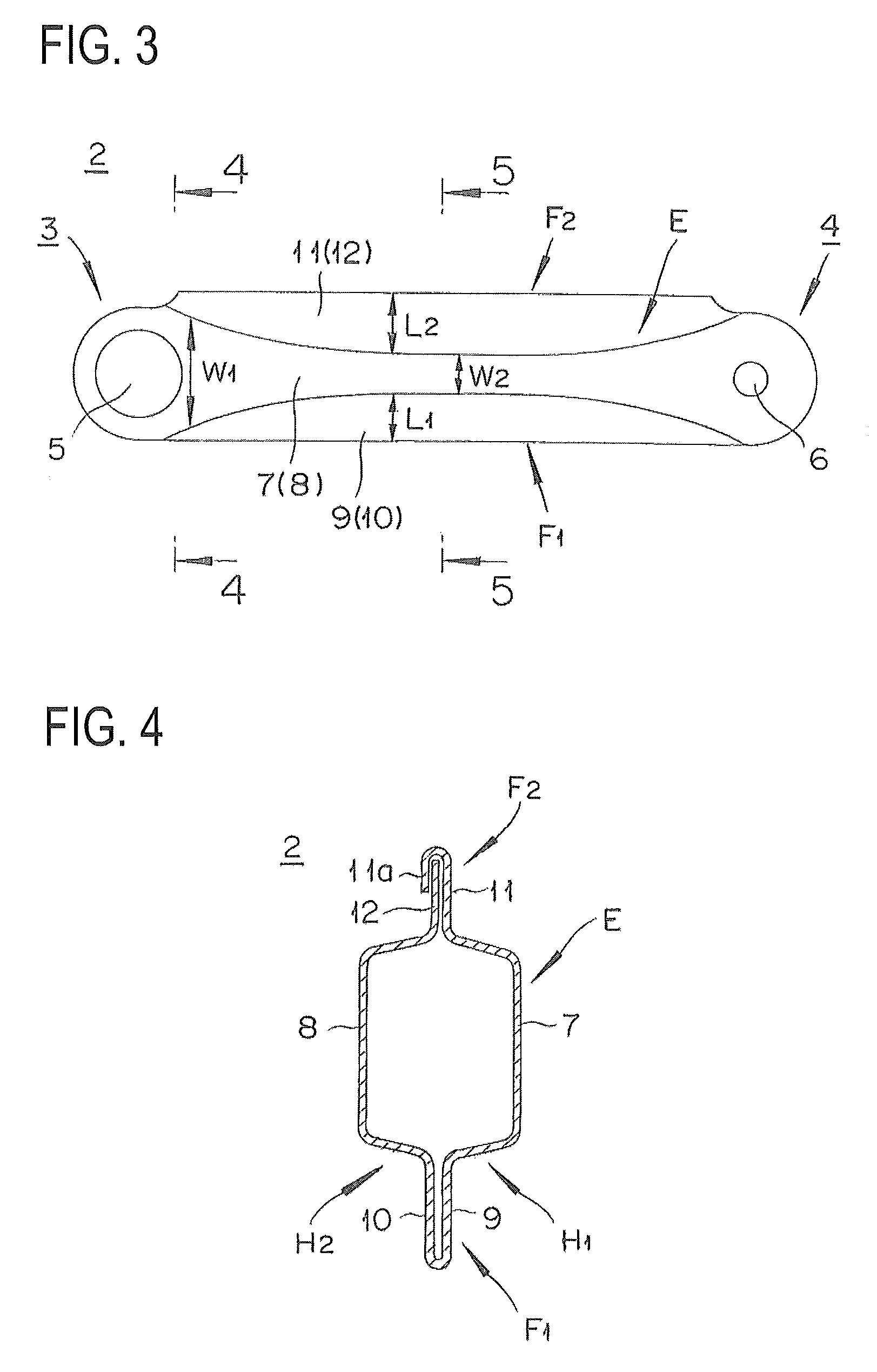
[0012]The product shows a sufficient strength or rigidity against repetitive compressive and tensile forces as said main part is formed to have a rectangular shape in the side view and the flange parts serve as reinforcement members.
[0013]Furthermore, there is an additional advantage in this design that a variety of arm components can be manufactured by providing a communicating hole in each end of both half members in forming a connecting part on both ends of the axial direction of the main part, inserting a collar in said communicating hole, and appropriately modifying the inner diameter of the communicating hole in each application.
[0014]The main body part should preferably be constituted in such a way as to have an arc-shaped outer edge part formed in such a way that a curved protrusion part changes its width gradually from wider in the vicinity of the connecting part and narrower in the middle. This makes it possible for the arm component to have a uniform strength over its entirety and can be safely used for applications where tensile and compressive forces occur repetitively.
[0015]Moreover, since both flange parts are formed utilizing, so to speak, excess thickness, reducing the removed portions to provide a better material yield, thus making it beneficial from the cost standpoint as well. In other words, the first and second flange parts exist extending from the curved protrusion part formed wider in the vicinity of the connecting part and narrower in the middle, and the entire main body part is formed in a rectangular shape as it is viewed from a side, so that the flange parts that are continuing from the curved protrusion part of the curved protrusion part that is formed narrower function as reinforcement members with ample thickness, so that the component provides a sufficient strength or rigidity against compressive and tensile forces repetitively applied.
[0016]The main body part and the connecting part should preferably made of a sheet of high tensile strength steel. This makes the entire arm component for vehicles light and strong.

Problems solved by technology

However, this suspension arm requires the bottom walls of the connection indentations to be jointed by welding so that it does not eliminate welding process completely, thus making its manufacture a complicated, time-consuming, and cost-expensive one.
Moreover, this suspension arm tends to be susceptive to distortions and deformations and is disadvantageous from the standpoint of strength and rigidity due to the fact that it does not have a closed cross-section but rather that its back member and each arm half member are formed to have a rectangular cross-section with one side being open despite the fact that the connection indentations are welded together.
Especially when such a structure having only the right arm half member and the left arm half drooping down from the left and right sides of the back member is subjected to repeated compressive and tensile forces as in the case of a suspension arm, its resistance against compressive forces tends to be weak although it provide some rigidity against tensile forces to a degree.

Method used


Image

  • Arm component for vehicles and its manufacturing method
  • Arm component for vehicles and its manufacturing method
  • Arm component for vehicles and its manufacturing method

Examples


Embodiment Construction

[0032]An embodiment of the present invention is described below.

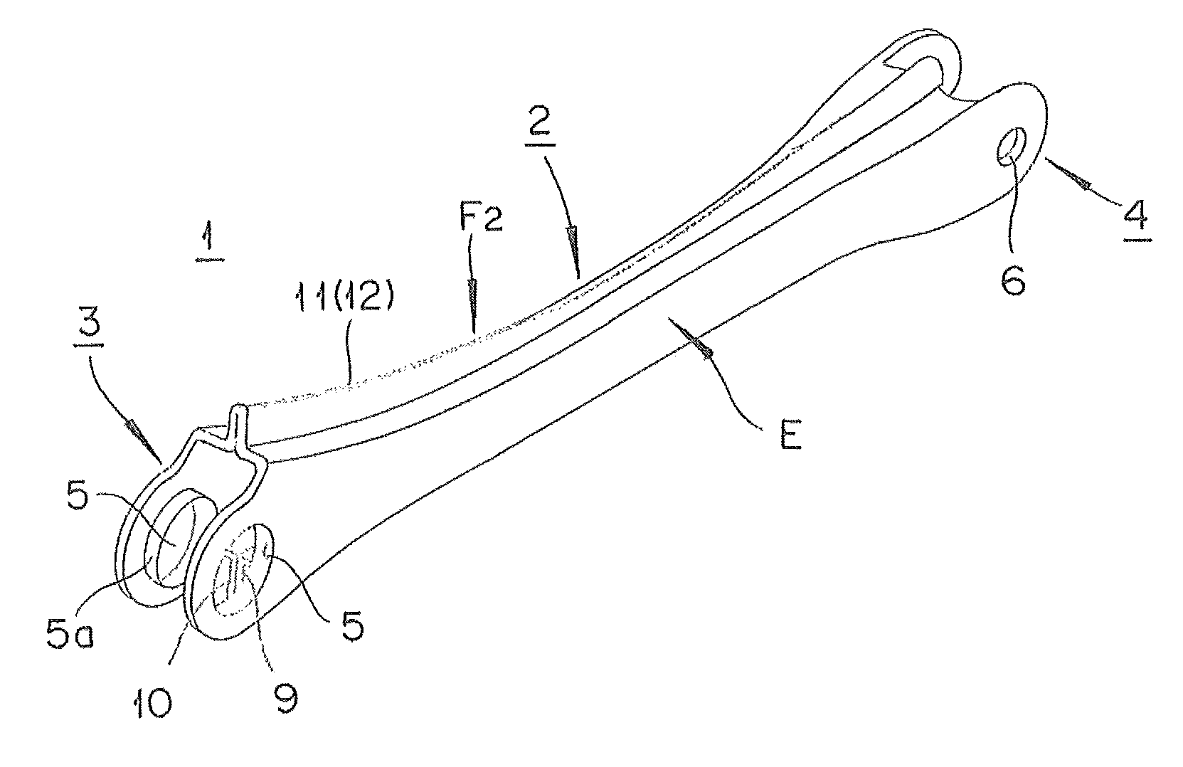
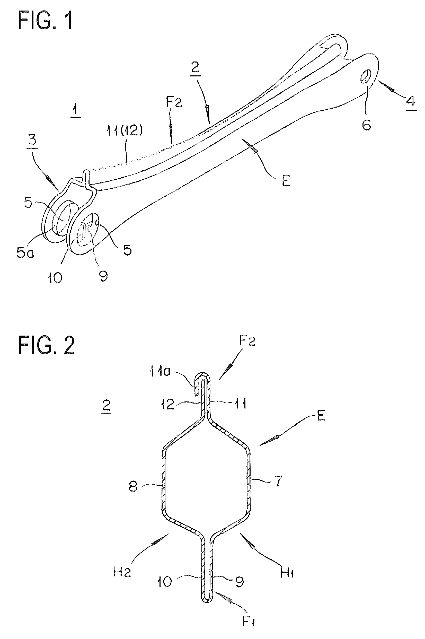
[0033]As shown in FIG. 1, the arm component for vehicles according to the present invention is intended to be used for a suspension arm 1 for vehicles, comprising: a longish main body part 2, connecting parts 3 and 4 provided on both ends of the main body part 2. The connecting part 3 is formed with a communicating hole 5 of a large diameter, into which a bush is pressed in, in order to connect with a shaft member (not shown) that is protruding from the body side via an elastic member such as rubber, and the connecting part 4 is formed with communicating hole 6, into which a bolt (not shown) is inserted from the wheel side to allow them to be connected by a nut.

[0034]As shown in FIG. 2, the expanded part E of the main body part 2 comprises: curved protrusion parts 7 and 8 that extend along the axial direction and protrude outward simultaneously; and a pair of half members H1 and H2 whose cross-sections perpendicular to ...


PUM

PropertyMeasurementUnit
widthaaaaaaaaaa
tensile strengthaaaaaaaaaa
forcesaaaaaaaaaa

Abstract

Disclosed herein is a suspension arm component for vehicles with sufficient strength or rigidity to withstand repetitive compressive and tensile forces, and a method for manufacturing such a component by pressing or hemming process alone, without recourse to any welding process, forming quickly and simply, a process with advantages in terms of material yield and cost. The suspension arm component for vehicles includes first flange pieces as well as second flange pieces, and a pair of half members, each having a hat-like shaped cross-section perpendicular to its axis, are joined together to protrude the first flange part and the second flange part from an expanded part, where both the first flange part and the second flange part extend linearly along the axis of the main body part. The main body part presents a rectangular shape in its side view.

Description

CROSS-REFERENCE TO RELATED APPLICATIONS[0001]This application is a national stage application (under 35 U.S.C. §371) of PCT / JP2012 / 056573, filed Mar. 14, 2012, which claims benefit of Japanese Patent Application No. 2011-055484, filed Mar. 14, 2011. Both of the aforementioned applications are incorporated herein by reference.TECHNICAL FIELD[0002]The present invention relates to an arm component for vehicles and its manufacturing method.BACKGROUND TECHNOLOGY[0003]Arm components for vehicles, such as suspension arms that connect car bodies with wheels or radius rods that connect sub frames to wheel side structures, need to have sufficient rigidities in order to resist or to transmit large forces that are applied in propelling or braking the vehicles.[0004]An arm component such as those mentioned above is typically constituted of a tube with a specified outer diameter and a wall thickness having a connecting bracket welded on one end and a connecting collar welded on the other end, whe...

Claims


Application Information

Patent Timeline
Patent Type & Authority Patents(United States)
IPC IPC(8): B60G9/02
CPCB60G2206/11B60G2206/722F16C7/08B60G7/001F16C2326/05Y10T29/49622B21D53/88B60G7/00B60G7/02B60G2206/00
Inventor UENO, MASAKIKUNIHARA, HITOSHI
Owner YOROZU CORP
Learn More