
Label printer

a label printer and label technology, applied in the field of printing machines, can solve the problems of inconvenient operation, hard to change the scroll, inconvenient to change, etc., and achieve the effects of convenient user change or assembly

Inactive Publication Date: 2014-06-17
POSTEK ELECTRONICS
View PDF7 Cites 2 Cited by
  • Summary
  • Abstract
  • Description
  • Claims
  • Application Information

AI Technical Summary

Benefits of technology

[0016]When implementing the label printer of the present invention, the following advantageous effects can be achieved.
[0017]1) It is convenient to change or assemble the consumable with the label printer of the present invention, the right side of the passage between the printer head module and the rubber roller and the mechanism module is opened after opening the pinch plate of the printer head module, and the consumable can be passed or removed through the passage without being cut off.
[0018]2) It is more convenient for users to change or assemble the consumable as the label printer of the present invention is opened at its sides which enlarge the space for user to change or assemble to consumable, avoiding damaging the desktop printer by mis-operation when changing the scroll resulting from the small space for passing the paper.
[0019]3) The label printer of the present invention is in a compact structure to occupy small space.

Problems solved by technology

And it is hard to change scrolls as the space for media going through are too small if opens at the top.
However, with the present printers whose covers can be flipped forward and backward, the label paper must pass through between the top cover and bottom housing, which is inconvenient to operate.
However, it is hard to operate when assembling the consumable as the side support points and the printer head module of the commercial, desktop or mini label printer in the prior art are always closed, resulting in that the consumable can only be passed through the small close gap between the printhead module and the rubber roller and the mechanism module.
And it is inconvenient to operate as the consumable must be cut off to pass through the small passage when changing the consumable.
In a word, it is hard to operate when changing scrolls due to the limited space for paper passing through in traditional desktop printer, and it is very likely to damage the desktop printer and shorten the product life if mis-operated when changing the scrolls.

Method used


Image

  • Label printer
  • Label printer
  • Label printer

Examples


Embodiment Construction

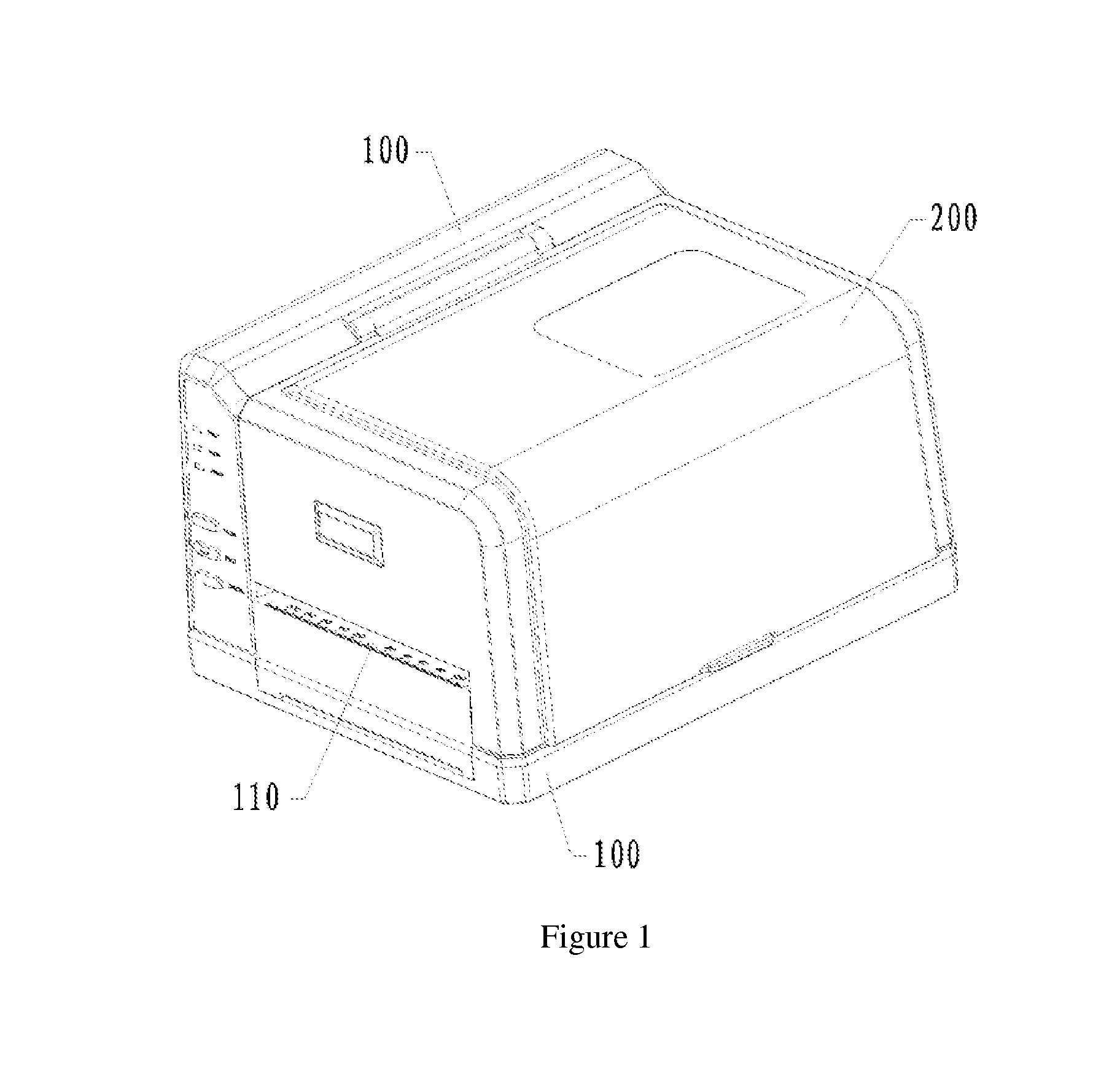
[0035]Referring to FIG. 1, in a specific embodiment of a label printer in the present invention, the label printer comprises a stationary housing 100 and a side cover 200 which are rotationally connected. The top and at least one side of the stationary housing 100 are opened, and the side cover 200 covers the opening of the stationary housing 100. A paper outlet 110 can be formed when the side cover 200 and the stationary housing 100 are closed up.

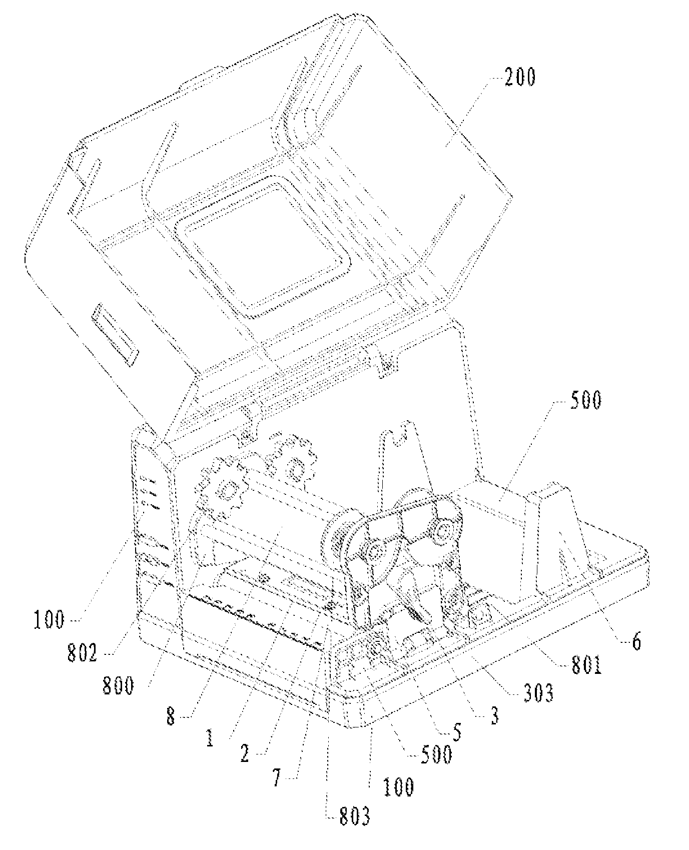
[0036]Referring to FIG. 2, a mechanism module is fixed in the stationary housing 100, and the paper outlet 110 is located at one side of the mechanism module while the rubber roller 7 of the mechanism module is parallel to the plane of the paper outlet 110. The mechanism module comprises a mechanism base 500 fixed on the bottom of the stationary housing 100 and a printer module frame 8 fixed on the mechanism base 500. At least two fixed shafts are set between a first side plate 800 and a second side plate 801 of the printer module frame 8,...


PUM


Abstract

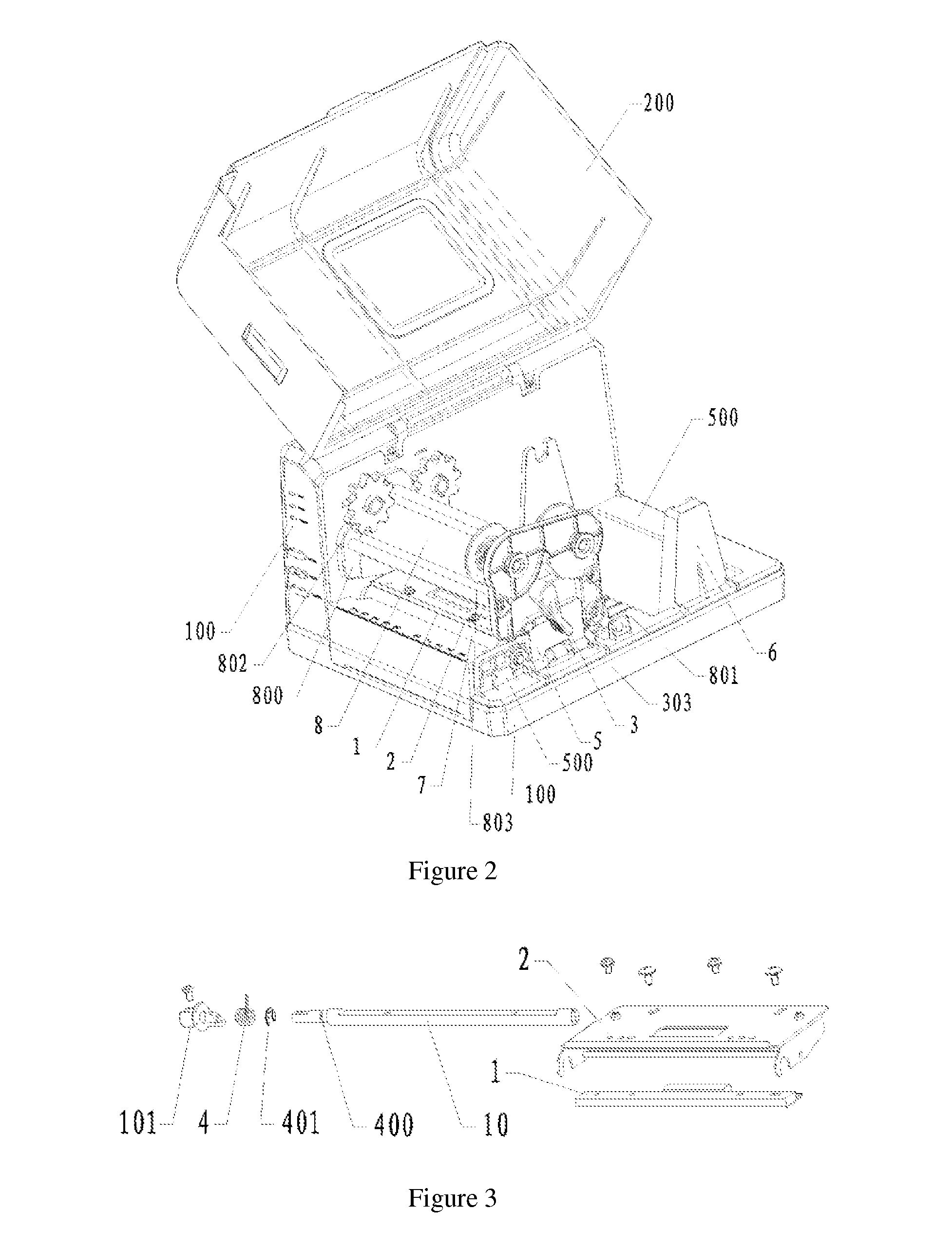
A label printer is provided. The label printer comprises a stationary housing (100) and a side cover (200) which are rotationally connected; a mechanism set is fixed in the stationary housing; at least two fixed shafts are set between a first side plate (800) and a second side plate (801) of the printer module frame; a pinch plate (5) used to support the second side plate is rotationally installed at the side of the mechanism base; a printer set (10,2,1) between the first side plate and the second side plate. The label printer in the invention is convenient to change or assemble the consumable.

Description

CROSS-REFERENCE TO RELATED APPLICATION[0001]The present application is a 371 of international application No. PCT / CN2010 / 075394 filed on Jul. 22, 2010; the contents of which are hereby incorporated by reference.FIELD OF THE INVENTION[0002]The present invention relates to printers, more particularly, to a label printer.BACKGROUND OF THE INVENTION[0003]Currently, all the label printers in commercial model, desk-top model or mini model that used in the market are in a structure of opening at the top, that is to say, the housing of the printers can be opened at the top. Thus, the consumable only can be put into the printers through the top of them. And it is hard to change scrolls as the space for media going through are too small if opens at the top. It is always necessary to add outside paper frames to accommodate large rolls of labels if multitudinous printing tasks are demanded in the practical work process. However, with the present printers whose covers can be flipped forward and ...

Claims


Application Information

Patent Timeline
Patent Type & Authority Patents(United States)
IPC IPC(8): B41J3/407B41J15/04
CPCB41J3/4075B41J11/0045B41J29/02B41J15/042B41J29/13
Inventor LV, GAORENZHENG, YUEQINZHAO, SENBINGDENG, HAIYUNXIE, RONGCHEN, LIANG
Owner POSTEK ELECTRONICS
Learn More