Variable stiffness positioning device for railway vehicle bogie axle box

a positioning device and railway vehicle technology, applied in the direction of axle box mounting, railway components, bogies, etc., can solve the problems of reduced vehicle operation quality, increased risk of train derailment, complex impact and vibration, etc., to improve vertical deflection, improve snaking critical operation speed, and increase longitudinal compression stiffness

Active Publication Date: 2018-03-20
CRRC YANGTZE CO LTD
View PDF18 Cites 0 Cited by
  • Summary
  • Abstract
  • Description
  • Claims
  • Application Information

AI Technical Summary

Benefits of technology

[0020]Further, the rigid outer cover of the elastomer pre-compression device is detachably embedded into a side face mounting hole of the guide frame of the side frame, and the other metal bearing plate of the large-stiffness elastic element is propped or hanged on the side face of the axle box bearing saddle. In this way, the longitudinal elastomer is designed to be of a detachable structure, thereby being very convenient to assemble, maintain and change.
[0021]As a third preferable solution the vertical elastomer includes an inner metal supporting sleeve with a conical surface outer wall and an outer metal supporting sleeve with a conical surface inner wall, a trumpet-shaped rubber sleeve vulcanized into an entirety with the inner metal supporting sleeve and the outer metal supporting sleeve is arranged there between, so that the vertical elastomer is of a conical platform-shaped structure on the whole. In this way, the vertical elastomer is not only simple in structure, strong in universality and convenient to disassemble, assemble and overhaul, and the trumpet-shaped rubber sleeve therefore forms a certain included angle with the vertical plane to effectively play the advantages of shear elasticity and compression combination and enable an axle box to obtain larger vertical deflection and proper longitudinal and horizontal stiffness.
[0022]Further, a cylindrical surface extension segment is smoothly arranged at the upper part of the conical surface inner wall of the outer metal supporting sleeve, the cylindrical surface extension segment is in vulcanization connection with the upper part of the outer wall of the trumpet-shaped rubber sleeve, and the upper and lower ends of the trumpet-shaped rubber sleeve are of concave curve surface structures. In this way, smooth, stable and reliable connection of the inner and outer walls of the trumpet-shaped rubber sleeve with the inner metal supporting sleeve and the outer metal supporting sleeve can be guaranteed, the bearing load is uniformly distributed and the service life thereof is effectively prolonged. Further, the trumpet-shaped rubber sleeve is integrally vulcanization molded by multiple layers of trumpet-shaped metal rings and multiple layers of trumpet-shaped rubber rings which are arranged in a staggered manner, and the included angles α between the generatrixes of the trumpet-shaped metal rings and the trumpet-shaped rubber rings with the conical surface inner wall of the outer metal supporting sleeve are 15-88 degrees. In this way, the combination number of the trumpet-shaped metal rings and the trumpet-shaped rubber rings can be adjusted according to demand and different included angles α can be designed to enable the vertical elastomer to satisfy the requirements of different elasticity and stiffness of the axle box and fully play the buffering and damping functions of the vertical elastomer. Further, the upper end of the outer metal supporting sleeve is embedded into a bottom surface mounting hole of the guide frame of the side frame, and the lower end of the inner metal supporting sleeve is embedded into a top face mounting hole of the axle box bearing saddle. In this way, the vertical elastomer is designed to be of a detachable structure, thereby being very convenient to assemble, maintain and change.
[0024]The present invention has the following advantages: the designed longitudinal elastomer has larger longitudinal compression stiffness when the longitudinal deformation displacement is very small, so that the railway vehicle can be guaranteed to have a higher snaking critical operation speed when operating on a straight line, and the acceleration operation demand of the vehicle is satisfied; when the longitudinal deformation displacement reaches a set numerical value, the longitudinal compression stiffness of the longitudinal elastomer starts to become small, so that when the railway vehicle passes by a curve, it can be guaranteed that the lateral force between wheel rails will not be too large to guarantee the curve operation safety of the vehicle, and thus the contradiction that the linear snaking critical operation speed of the vehicle and the curve passing performance of the vehicle cannot be compromised is effectively solved. Meanwhile, the designed vertical elastomer can both enable the axle box to obtain better vertical deflection and enable the axle box to obtain better lateral stiffness, and the vertical elastomer can also cooperate with the longitudinal elastomers on both sides to smoothly and stably achieve the two-stage variable stiffness property being soft at first and then becoming hard of the longitudinal elastomer, so as to effectively reduce the unsprung mass of the bogie, buffer the wheel rail impact of the vehicle, improve the dynamic performance of the vehicle and guarantee the operation safety of the vehicle to greatly perfect the operation quality of the railway vehicle.

Problems solved by technology

When the railway vehicle operates at a high speed on the rails, complex impact and vibration will be produced accordingly.
A traditional axle box bearing saddle and the guide frames on both ends of the side frame component adopt a rigid connection structure, which has the defects that the axle box bearing saddle and the guide frames of the side frame are rigidly positioned in a dry friction manner, the frictional force increases linearly to fail to adapt to the high-speed operation demand of the vehicle, moreover the lateral force of wheel rails is large, and thus the risk of train derailment is increased.
At a state of heavy load and high speed, when moving along the rails, the vehicle wheel pairs are easier to initiate yaw motion of the vehicle body, resulting in greatly reduced operation quality of the vehicle and will cause a vehicle derailment accident seriously.
At present, improving the snaking critical operation speed of the vehicle on the straight line and improving the passing performance of the vehicle on the curve are a pair of contradictions, and thus it is very hard to give consideration to both in the specific design of the elastic axle box suspension device of the vehicle bogie.
This is because, two main elastic axle box suspension devices cannot simultaneously satisfy the above-mentioned requirements at present: one is a vertical elastic device arranged between the top face of the axle box bearing saddle and the bottom surface of the guide frame of the side frame, although the device has a certain function on vertical damping of the bogie, the axle box bearing saddle is in rigid hard contact with the bottom surface of the guide frame of the side frame, and no buffering device is available, so that the inhibitory effect on lateral vibration and longitudinal vibration of the bogie is poor, moreover the structural design is quite complex, the parameter matching difficulty is very large, the assembly universality is poor, and the snaking critical operation speed of the vehicle on the straight line and the passing performance requirement of the vehicle on the curve cannot be compromised in the case of acceleration and heavy load.
Another condition is that a vertical elastic device is arranged, and longitudinal elastic devices are arranged between the axle box bearing saddle and both sides of the guide frame of the side frame, in this way, damping and control on the longitudinal impact of the bogie are easier to achieve, but the stiffness of the front and back longitudinal elastic devices are invariable, due to the limitation of this structural form, with the increase of the displacement, the load of the bogie increases linearly or in an equal proportional increase manner, the snaking critical operation speed of the vehicle on the straight line and the passing performance requirement of the vehicle on the curve cannot be completely compromised either, and meanwhile the risk of train derailment also exists, so that the functions of the elastic axle box suspension device are greatly reduced.

Method used


Image

  • Variable stiffness positioning device for railway vehicle bogie axle box
  • Variable stiffness positioning device for railway vehicle bogie axle box
  • Variable stiffness positioning device for railway vehicle bogie axle box

Examples


Embodiment Construction

[0034]To better explain the present invention, the main contents of the present invention will be further illustrated below in combination with the accompanying drawings and specific embodiments, but the contents of the present invention are not merely limited to the following embodiments.

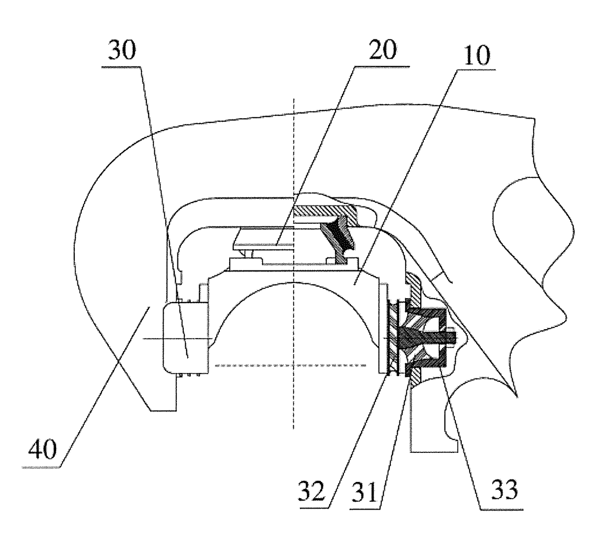
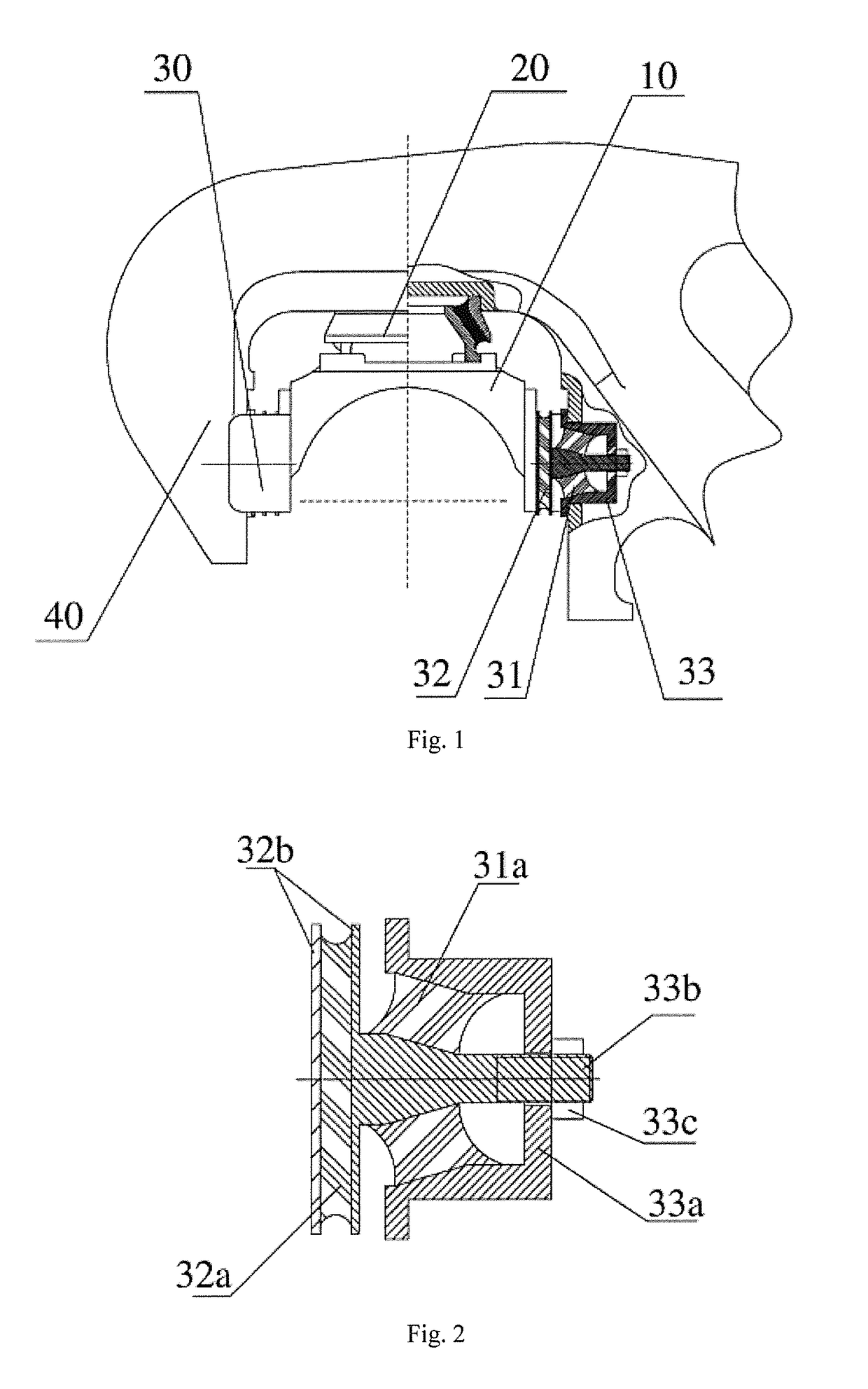
[0035]As shown in FIG. 1, a variable stiffness positioning device for a railway vehicle bogie axle box provided by the present invention is mainly composed of a vertical elastomer 20 arranged between the top face of an axle box bearing saddle 10 and the bottom surface of a guide frame 40 of a side fame, and longitudinal elastomers 30 respectively arranged between the axle box bearing saddle 10 and the front and back side faces of the guide frame 40 of the side fame. The longitudinal elastomer 30 is provided with a small-stiffness elastic element 31 and a large-stiffness elastic element 32, and the small-stiffness elastic element 31 is arranged in an elastomer pre-compression device 33 and is serial...


PUM


Abstract

The present invention provides a variable stiffness positioning device for a railway vehicle bogie axle box. The variable stiffness positioning device includes a vertical elastomer arranged between the top face of an axle box bearing saddle and the bottom surface of a guide frame of a side fame, and a longitudinal elastomer arranged between the axle box bearing saddle and the front and back side faces of the guide frame of the side fame, the longitudinal elastomer is provided with at least one small-stiffness elastic element and a large-stiffness elastic element, and the small-stiffness elastic element is arranged in an elastomer pre-compression device and is serially arranged with the large-stiffness elastic element under the action of a pre-compression load F1. The longitudinal elastomer has a larger longitudinal compression stiffness when the longitudinal deformation displacement is very small, so that the railway vehicle can be guaranteed to have a higher snaking critical operation speed when operating on a straight line, and the acceleration operation demand of the vehicle is satisfied; when the longitudinal deformation displacement reaches a set numerical value, the longitudinal compression stiffness of the longitudinal elastomer starts to become small, so that when the railway vehicle passes by a curve, it can be guaranteed that the lateral force between wheel rails will not be too large, and thus the curve operation safety of the vehicle is guaranteed.

Description

FIELD OF THE INVENTION[0001]The present invention relates to the design and manufacture technology of railway vehicle bogies, and particularly, to a variable stiffness positioning device of a railway vehicle bogie axle box.BACKGROUND OF THE INVENTION[0002]A railway vehicle is a special vehicle operating on special rails, and when operating along the special rails, the railway vehicle can be self-oriented without being controlled in direction. A bogie is one of the most important components on the railway vehicle, and it supports the weight of an entire commodity and the weight of the vehicle body. The traditional bogies is mostly of a structure with three large parts, namely, two side frame components and a swing bolster component, guide frames on both ends of the side frame components are installed on front and back wheel pair components through axle box bearing saddles and bearing devices, and both ends of the swing bolster component are installed in central square frames of the s...

Claims


Application Information

Patent Timeline
Patent Type & Authority Patents(United States)
IPC IPC(8): B61F5/30B61F5/36
CPCB61F5/305B61F5/36B61F5/301B61F5/30
Inventor YAN, ZHIXIONGJIANG, RUIJINZHANG, LIANGWEICUI, HONGLIU, FENGWEILIU, WENLIANGFU, TIEJUNDAN, ZHAOJUNWANG, PINGPING
Owner CRRC YANGTZE CO LTD
Why Eureka
Try Eureka