

Aircraft nacelle air intake incorporating optimized ice-treatment hot air injection means
- Summary
- Abstract
- Description
- Claims
- Application Information
AI Technical Summary
Benefits of technology
Problems solved by technology
Method used
Image

Examples
Embodiment Construction
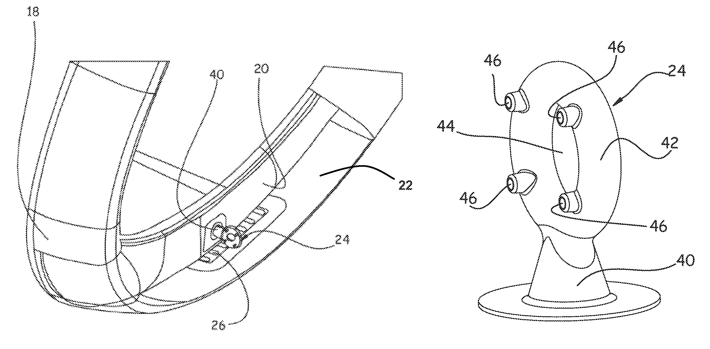
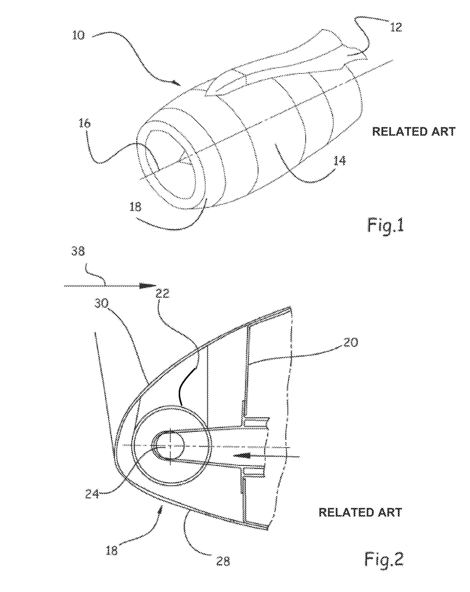
[0032]FIG. 2 shows an air intake 18 of an aircraft nacelle. The air intake makes it possible to channel an air flow referenced by the arrow 38 to the power plant.
[0033]The front part of the air intake describes an essentially circular shape that extends in a plane that can be essentially perpendicular to the longitudinal axis, or not perpendicular, with the front part that is located just before 12 o'clock. However, other forms of air intake can be considered.
[0034]The invention relates more particularly to a nacelle that integrates a frost treatment that consists in using the hot air that is drawn off at the power plant.
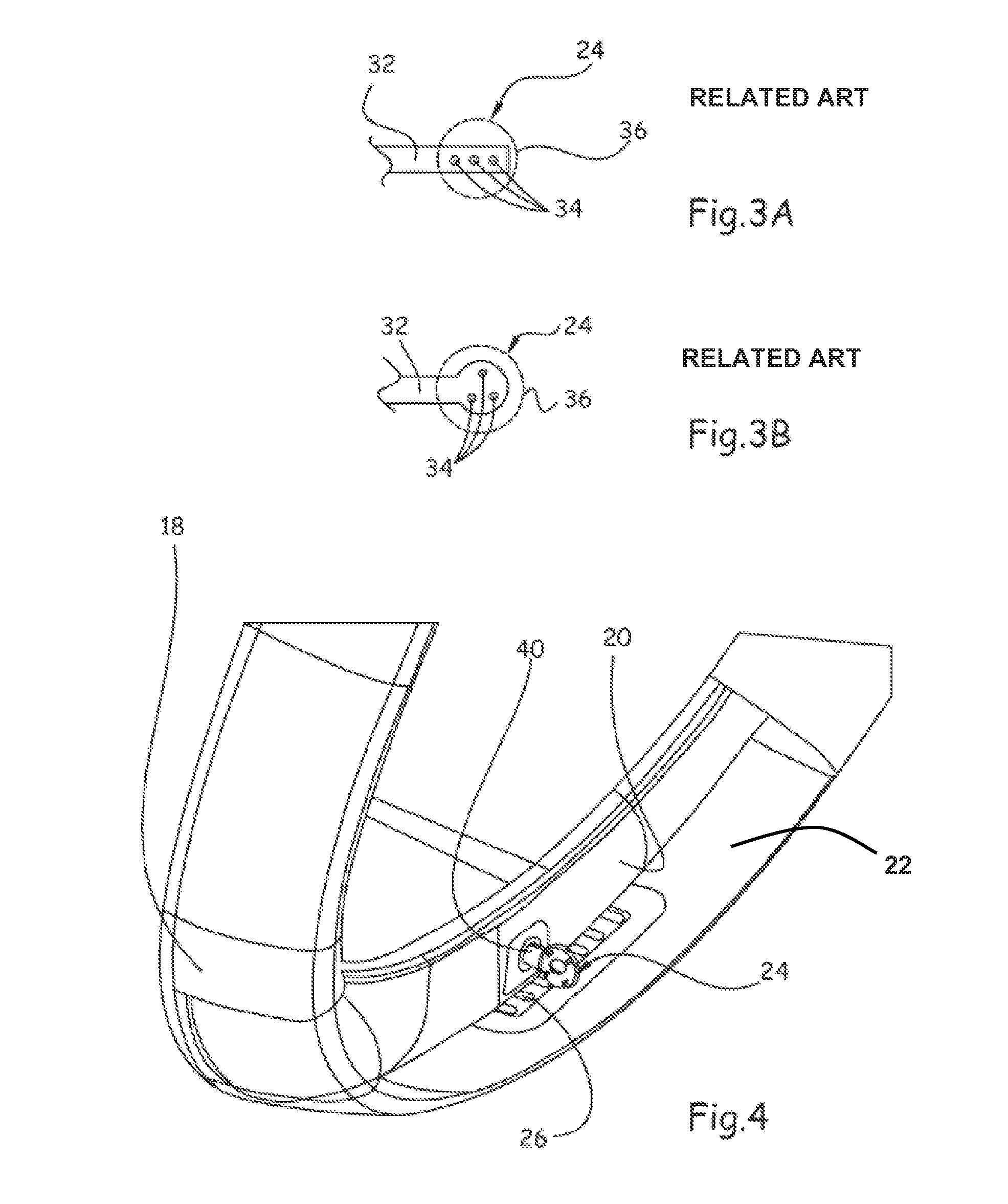
[0035]According to one embodiment, a nacelle comprises a partition that is called a front frame 20 that with the air intake 18 borders a pipe 22 that extends over the entire circumference of the nacelle and that has a D-shaped cross-section.
[0036]According to one embodiment, this pipe 22 comprises means 24 for localized injection of hot air.
[0037]In addition, the pi...
PUM
 Abstract
Description
Claims
Application Information