Ram intake unit having a sound absorbing structure

a technology of ram air intake and sound absorption, which is applied in the direction of combustion air/fuel air treatment, machines/engines, cycles, etc., to achieve the effect of reducing the number of components used, avoiding the removal of acoustic material from the ram air intake duct, and high sound absorption

a technology of ram air intake and sound absorption, which is applied in the direction of combustion air/fuel air treatment, machines/engines, cycles, etc., to achieve the effect of reducing the number of components used, avoiding the removal of acoustic material from the ram air intake duct, and high sound absorption

US8162101B2Active Publication Date: 2012-04-24KAWASAKI MOTORS LTD

Image

  • Ram intake unit having a sound absorbing structure
  • Ram intake unit having a sound absorbing structure
  • Ram intake unit having a sound absorbing structure

Examples


Embodiment Construction

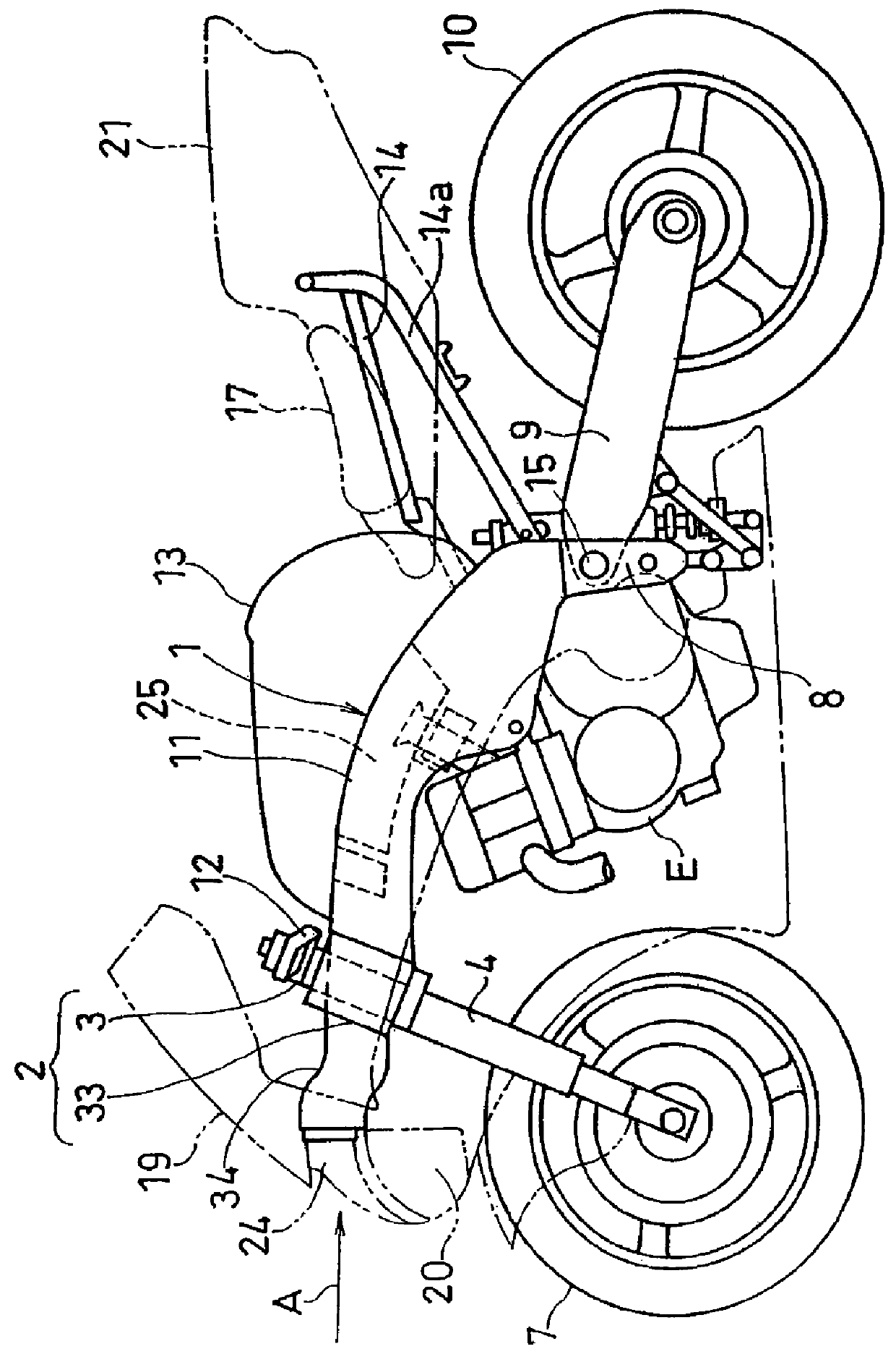
[0053]A preferred embodiment of the present invention will be described in detail with reference to the accompanying drawings. Of those accompanying drawings, FIG. 1 schematically illustrates a side view of a motorcycle equipped with a ram intake unit according to the preferred embodiment of the present invention.

[0054]Referring to FIG. 1, the motorcycle shown therein includes a motorcycle frame structure 1 having a main frame 11 and a head block 2 at a front portion of the main frame 11. This head block 2 includes a head tube 3 formed integrally therewith, and a front fork assembly 4 is rotatably supported by the head tube 3 through a steering shaft (not shown), with a front wheel 7 rotatably supported at a lower end thereof for rotation in any manner known to those skilled in the art.

[0055]A swingarm bracket 8 is secured to a lower intermediate portion of the motorcycle frame structure 1, and a swingarm 9 is pivotably supported by the swingarm bracket 8 through a pivot pin 15 at a...


PUM


Abstract

A ram intake unit mounted on a front portion of a frame structure of a motorcycle includes an acoustic material disposed along an inner wall of a ram air intake duct for absorbing induction noises, which duct forms an induction system through which an incoming wind can be introduced towards a motorcycle combustion engine, and a holder disposed inwardly of the acoustic material for securing the acoustic material to the ram air intake duct.

Description

CROSS REFERENCE TO THE RELATED APPLICATION[0001]This application is based on and claims Convention priority to Japanese patent applications No. 2008-241240 and No. 2008-241241, both filed Sep. 19, 2008, the entire disclosure of each of which is herein incorporated by reference as a part of this application.BACKGROUND OF THE INVENTION[0002]1. Field of the Invention[0003]The present invention relates to a ram intake unit employed in a front portion of a motorcycle.[0004]2. Description of the Related Art[0005]In a motorcycle of a kind equipped with a so-called ram induction system, in which an air intake opening for introducing towards a combustion engine an air eventually forming an air-fuel mixture with a fuel, is mounted in a front region of a motorcycle frame structure, an external air is supplied through the air intake opening at the front portion of the motorcycle frame structure to the combustion engine by way of a ram air intake duct and an air cleaner during the travel of the ...

Claims


Application Information

Patent Timeline
24 Apr 2012
Publication
US8162101B2
IPC
F02M35/00; F02B77/04; F01N13/08; B62D61/02; F02M35/02; F02M35/10; F02K1/08
CPC
F02M35/10144; F02M35/10334; F02M35/10354; F02M35/162; F02M35/1272; F02M35/1277
Inventors
ONO, TAKAHIRO