Air intake system and method for gas turbine

A technology of gas turbine and air intake system, applied in the field of air intake system, which can solve the problems of gas turbine power and efficiency reduction, increase of intake pressure loss, and non-simultaneous occurrence, so as to ensure smooth flow, work efficiency, and use The effect of longevity

Inactive Publication Date: 2015-09-09
江苏华强新能源科技有限公司
View PDF0 Cites 11 Cited by
  • Summary
  • Abstract
  • Description
  • Claims
  • Application Information

AI Technical Summary

Problems solved by technology

[0003] The gas turbine uses air as the working medium, and the quality and purity of its inlet air are the prerequisites for improving the performance and reliability of the unit, because the air contains more or less various inorganic and organic particulate impurities, which will be produced in the flow part of the gas turbine Erosion, fouling and corrosion, but generally do not occur at the same time. For power station gas turbines, the erosion of dust particles on the blades is a more prominent problem, which has a great impact on the life of the unit; therefore, the air entering the gas turbine must be treated , to filter out impurities to improve the air quality at the inlet of the gas turbine compressor, and keep the inlet pressure drop within the allowable range to ensure the performance of the gas turbine. For the gas turbine, when the inlet air filter is polluted or frosted in winter, etc. When it is blocked, the intake pressure loss will increase significantly, and the loss of intake pressure will reduce the inlet pressure of the compressor. When the maximum pressure of the gas engine cycle is kept constant, the specific work of the compressor must be increased. At this time, the turbine’s The output will consume more power to drive the compressor, resulting in a reduction in the power and efficiency of the gas turbine; therefore, the intake filter system has a great economic impact on the gas turbine

Method used


Image

  • Air intake system and method for gas turbine
  • Air intake system and method for gas turbine
  • Air intake system and method for gas turbine

Examples


Embodiment 1

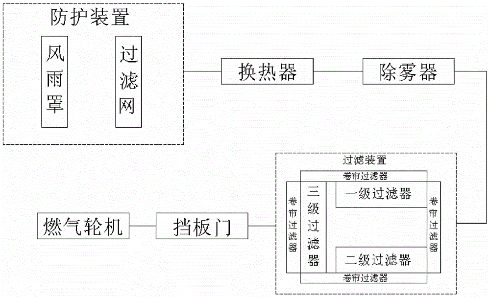
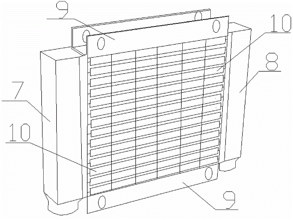
[0028] A gas turbine intake system provided in this embodiment has a structure such as Figure 1-4 As shown, it includes the intake pipe connected to the air intake of the internal combustion engine and the protective device connected through the intake pipe, heat exchanger, demister, filter device and baffle door, and the air intake pipe is also equipped with Pipeline muffler, the pipeline silencer is set between the deflector and the baffle door, the protective device is connected with the heat exchanger, the heat exchanger is connected with the filter device, and there is a demister between the heat exchanger and the filter, and the filter A diversion device is provided at one end of the outlet of the device, and a baffle door is provided at the outlet of the intake pipe, wherein:

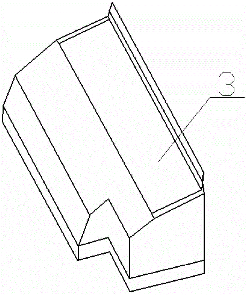
[0029] The protective device comprises a wind and rain cover 3 arranged at the entrance of the air intake duct and a filter screen arranged in the wind and rain cover 3,

[0030] The upper surf...


PUM


Abstract

The invention discloses an air intake system for a gas turbine. The air intake system comprises an air intake ducting connected with an air inlet of an internal-combustion engine, a protection device, a heat exchanger, a demister, a filter device and a baffle door, wherein the protection device, the heat exchanger, the demister, the filter device and the baffle door are connected through the air intake ducting; the protection device is connected with the heat exchanger; the heat exchanger is connected with the filter device; the demister is arranged between the heat exchanger and the filter device; a blast deflector is arranged at one end of the outlet of the filter device; and the baffle door is arranged at the outlet of the air intake ducting. The invention further discloses an air inlet method of the gas turbine. The air intake system of the gas turbine is simple in structure and performs multiple filtration on gas, so that the quality of the gas is ensured, and the service life of the gas turbine is prolonged. The air intake method of the gas turbine is simple and practicable to operate.

Description

technical field [0001] The invention relates to an air intake system, in particular to an air intake system on a gas turbine and a method thereof. Background technique [0002] Gas turbine is an advanced and complex complete set of power machinery equipment. It is a typical high-tech intensive product. As a high-tech carrier, gas turbine represents the comprehensive level of development of multiple theoretical disciplines and multiple engineering fields. It is the leading technology of the 21st century. The development of a gas turbine industry that integrates new technologies, new materials, and new processes is one of the important symbols of the country's high-tech level and scientific and technological strength, and has a very prominent strategic position; [0003] The gas turbine uses air as the working medium, and the quality and purity of its inlet air are the prerequisites for improving the performance and reliability of the unit, because the air contains more or les...

Claims


Application Information

Patent Timeline
Patent Type & Authority Applications(China)
IPC IPC(8): F02C7/055F02C7/05F02C7/08
Inventor 陈欣邬文泰
Owner 江苏华强新能源科技有限公司
Why Eureka
Try Eureka