System and method for cooling air intake

a technology of system and air intake, applied in the field of air cooling systems, can solve the problems of reducing combustion efficiency and increasing temperatures, and achieve the effect of increasing horsepower and torqu

Inactive Publication Date: 2007-04-03
THERMO TEC HIGH PERFORMANCE AUTOMOTIVE
View PDF4 Cites 13 Cited by
  • Summary
  • Abstract
  • Description
  • Claims
  • Application Information

AI Technical Summary

Problems solved by technology

Increased temperatures decrease the efficiency of combustion.

Method used


Image

  • System and method for cooling air intake
  • System and method for cooling air intake
  • System and method for cooling air intake

Examples


Embodiment Construction

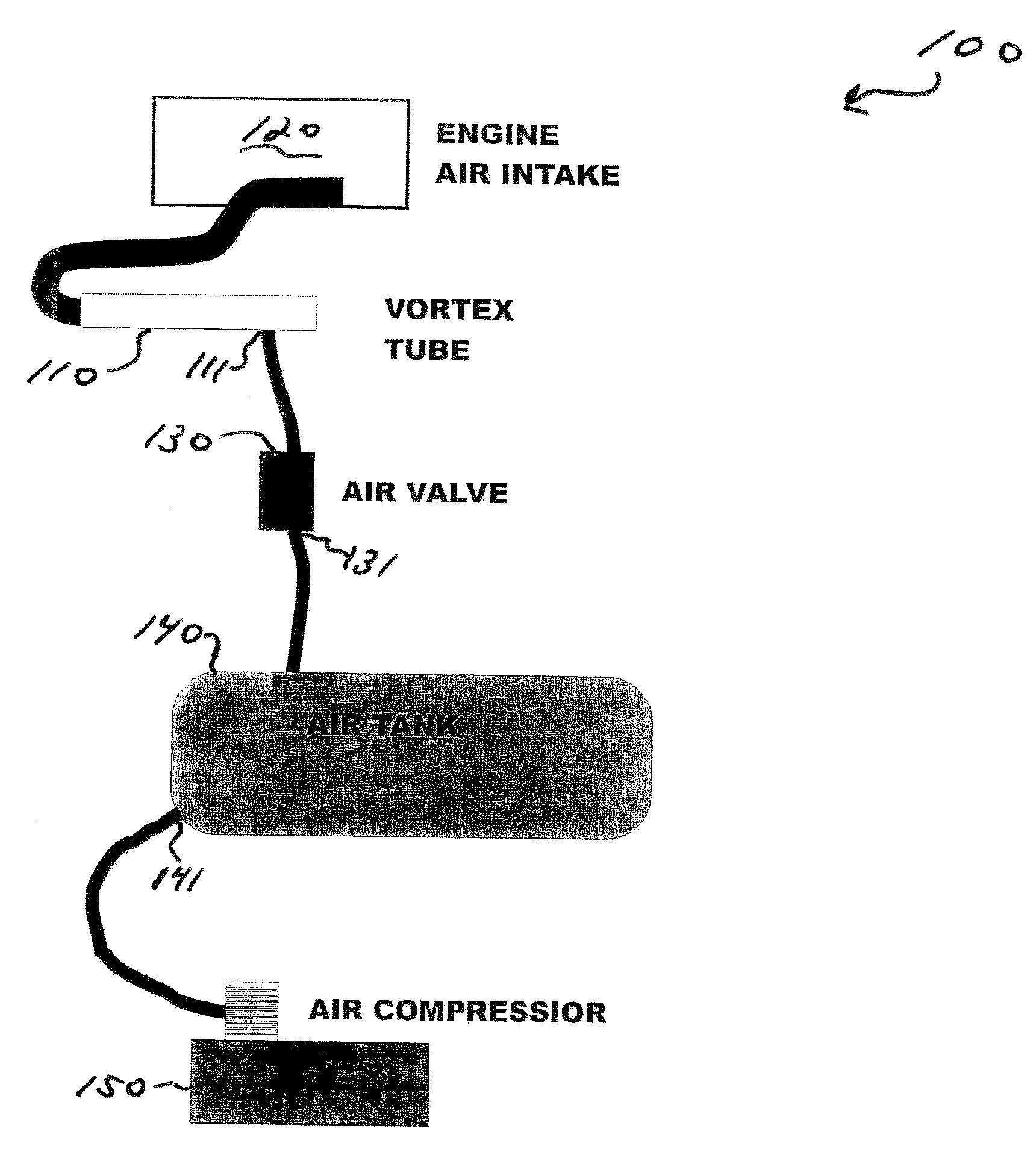
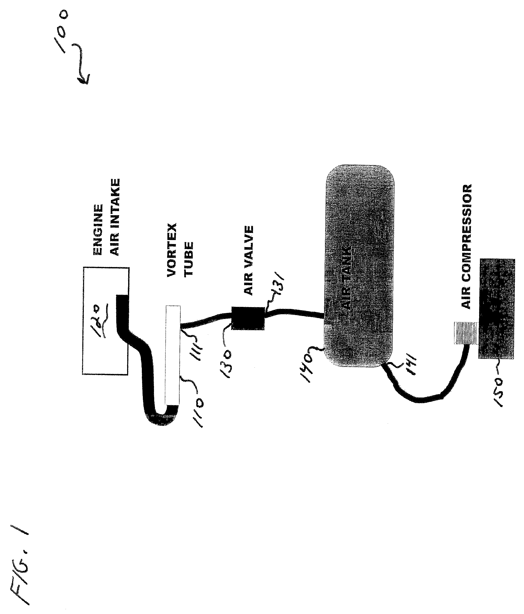
[0019]FIG. 1 illustrates an embodiment of a system 100 for increasing the horsepower and torque provided by an internal combustion engine, in accordance with various aspects of the present invention. The system 100 comprises a vortex tube 110 connected to an engine air intake 120 of an internal combustion engine (not shown) to provide cooled air to the engine air intake 120. The system 100 further comprises an air valve 130 connected to an input 111 of the vortex tube 110 to control a flow of air to the vortex tube 110. The system 100 also includes an air tank 140 connected to an input 131 of the air valve 130 to provide compressed air to the air valve 130. The system 100 also comprises an air compressor 150 connected to an input 141 of the air tank 140 to pressurize air within the air tank 140. The connections between the various elements 110, 120, 130, 140, and 150 may be accomplished using standard hoses, conduits, or tubing capable of holding the air pressures produced by the ai...


PUM


Abstract

A system and method for increasing the horsepower and torque provided by an internal combustion engine involve the use of a vortex tube to provide cooled air to the air intake of the engine. The system utilizes a source of compressed air such as provided by a compressor and air tank. The compressed air is injected into the vortex tube producing a heated stream of air and a cooled stream of air. The cooled stream of air is directed into the intake of the engine. The system enhances the air flow and drops the induction air temperature into the engine. An air valve may be used to control the flow of compressed air into the vortex tube.

Description

CROSS-REFERENCE TO RELATED APPLICATIONS / INCORPORATION BY REFERENCE[0001]This application claims the benefit of U.S. Provisional Application Ser. No. 60 / 588,298, filed Jul. 14, 2004, which is hereby incorporated by reference.TECHNICAL FIELD[0002]Certain embodiments of the present invention relate to air cooling systems. More particularly, certain embodiments of the present invention relate to a system and a method for providing cooled air to an internal combustion engine for increasing the horsepower and torque provided by the internal combustion engine.BACKGROUND OF THE INVENTION[0003]Engine performance of an internal combustion engine is affected by the temperature of the fuel therein. Increased temperatures decrease the efficiency of combustion.[0004]U.S. Pat. No. 5,558,069 to Stay describes an apparatus and method for cooling or heating fluids, such as fuel in a fuel system of an automotive vehicle. Compressed gas is delivered to a vortex tube or air amplifier so that the gas rap...

Claims


Application Information

Patent Timeline
Patent Type & Authority Patents(United States)
IPC IPC(8): F02M15/00
CPCF02M31/20F02M31/10F02M31/18Y02T10/126Y02T10/12
Inventor WHITE, JAMES E.
Owner THERMO TEC HIGH PERFORMANCE AUTOMOTIVE
Why Eureka
Try Eureka