Air intake for aircraft nacelle, and propulsion assembly including such air intake

a technology for aircraft nacelles and air intakes, which is applied in the direction of power plant arrangements/mountings, air-flow influencers, and jet propulsion plants. it can solve the problems of local deformations or even the and the vibration and/or shock of the turbojet engine that reverberates on the entire nacelle, so as to limit the risk of deformation or ruin of the air intak

Inactive Publication Date: 2010-12-23
SAFRAN NACELLES
View PDF14 Cites 12 Cited by
  • Summary
  • Abstract
  • Description
  • Claims
  • Application Information

AI Technical Summary

Benefits of technology

[0009]The present invention aims in particular to provide means making it possible to limit this risk of def...

Problems solved by technology

In case of deformation or rupture of vane of the fan (commonly referred to as “FBO” for “Fan Blade Out”), the turbojet engine causes very significant vibrations and/or shocks that reverberate on the entire nacelle, and ...

Method used


Image

  • Air intake for aircraft nacelle, and propulsion assembly including such air intake
  • Air intake for aircraft nacelle, and propulsion assembly including such air intake
  • Air intake for aircraft nacelle, and propulsion assembly including such air intake

Examples


Embodiment Construction

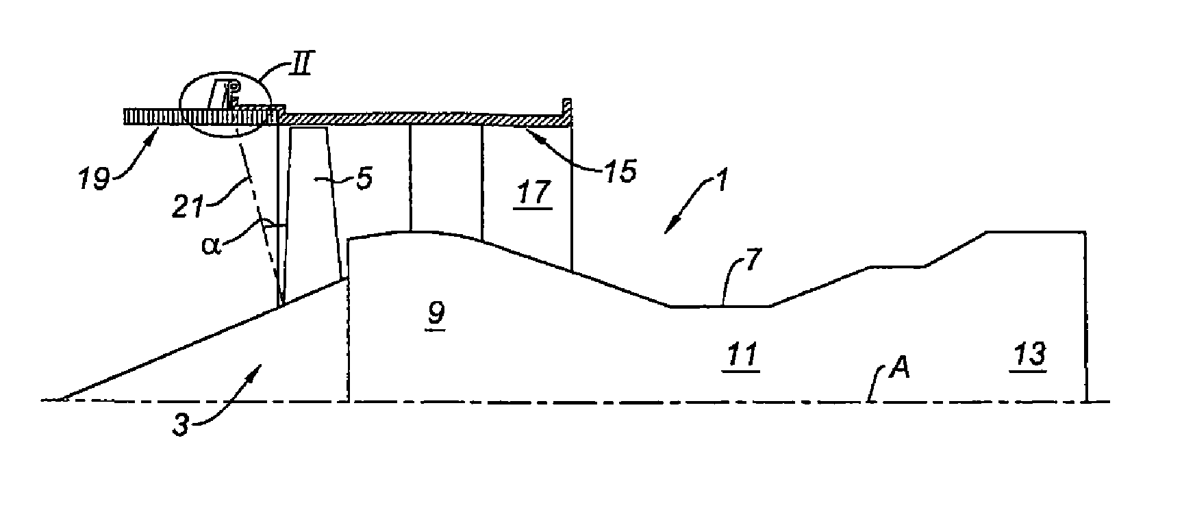
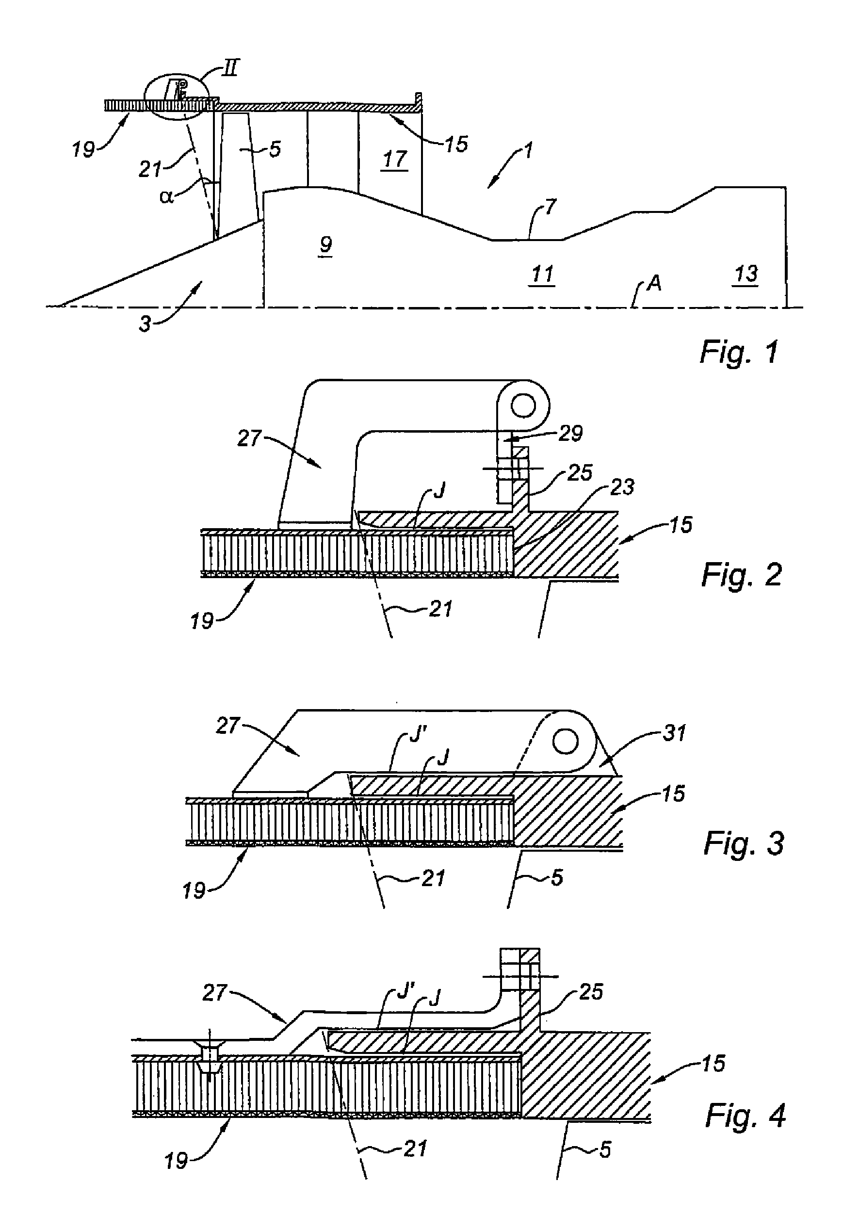
[0039]In the following, the terms “upstream” and “downstream” must be understood in relation to the direction of circulation of the air and gases in the propulsion assembly, and correspond in this case to the left and right, respectively, of the figures.

[0040]In reference now to FIG. 1, we have diagrammatically illustrated an aircraft turbojet engine, including, in its upstream portion, a fan 3 provided with vanes 5, and in its downstream portion the engine 7 strictly speaking, comprising as known in itself its compression 9, combustion 11 and propulsion 13 stages.

[0041]Around the fan 3 and the compression stage 9, is a fan casing 15, defining a cold air stream 17 with the engine 1.

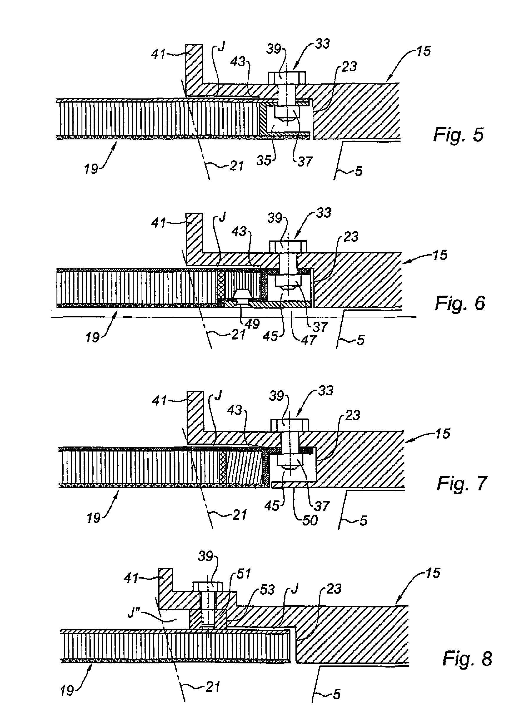
[0042]Upstream from this casing 15, and situated in the extension thereof, is a tubular member 19, frequently designated by “shroud”, which is part of the nacelle designed to surround the turbojet engine 1.

[0043]More precisely, this shroud 19 constitutes the inner face of the air intake of the nacelle, as...


PUM


Abstract

The invention relates to an air intake for an aircraft nacelle that comprises a shroud (19) that can be mounted on the fan casing (15) of a turbojet engine (1). The shroud (19) is sized so as to define a circumferential gap (J) relative to the casing (15). Punctual linking means (27, 33) between the shroud (19) and the casing (15) are discretely distributed at the periphery of said shroud (19).

Description

TECHNICAL FIELD[0001]The present invention concerns in particular an air intake for aircraft nacelle.BACKGROUND[0002]An airplane is propelled by one or several propulsion assemblies each comprising a turbojet engine housed in a tubular nacelle. Each propulsion assembly is attached to the plane by a mast generally situated under a wing or at the fuselage.[0003]A nacelle generally comprises a structure including an air intake upstream from the engine, a middle section designed to surround a fan of the turbojet engine, a downstream section housing thrust reverser means and designed to surround the combustion chamber of the turbojet engine, and generally ends with a jet nozzle whereof the outlet is situated downstream from the turbojet engine.[0004]The air intake comprises, on one hand, an intake lip adapted to allow optimal collection towards the turbojet engine of the air necessary to supply the fan and internal compressors of the turbojet engine, and on the other hand, a downstream s...

Claims


Application Information

Patent Timeline
IPC IPC(8): B64D33/02B64C1/40
CPCB64D33/02B64D2033/0206F05D2220/36F01D21/00F02C7/045B64D2033/0286
Inventor VAUCHEL, GUY BERNARDVALLEROY, LAURENT GEORGESBEILLIARD, STEPHANEBRAVIN, FABIEN
Owner SAFRAN NACELLES
Why Eureka
Try Eureka