Eureka AIR delivers breakthrough ideas for toughest innovation challenges, trusted by R&D personnel around the world.

Cargo restraint apparatus

Inactive Publication Date: 2014-06-24
STRONG YUN IND
View PDF1 Cites 4 Cited by
  • Summary
  • Abstract
  • Description
  • Claims
  • Application Information

AI Technical Summary

Benefits of technology

The invention is a cargo restraint apparatus that has a simple design, is less expensive and is easy to use. Its technical effects are to reduce the complexity and cost of cargo restraints while also making them more user-friendly.

Problems solved by technology

However, manufacturing costs of such a trigger member are expensive.
This increases volume of the apparatus.
Thus it is so difficult to operate the apparatus.

Method used


Image

  • Cargo restraint apparatus
  • Cargo restraint apparatus
  • Cargo restraint apparatus

Examples


Embodiment Construction

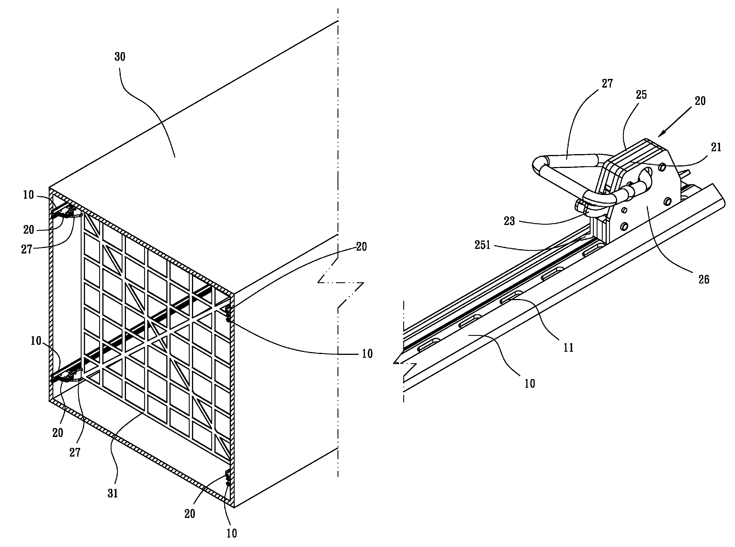
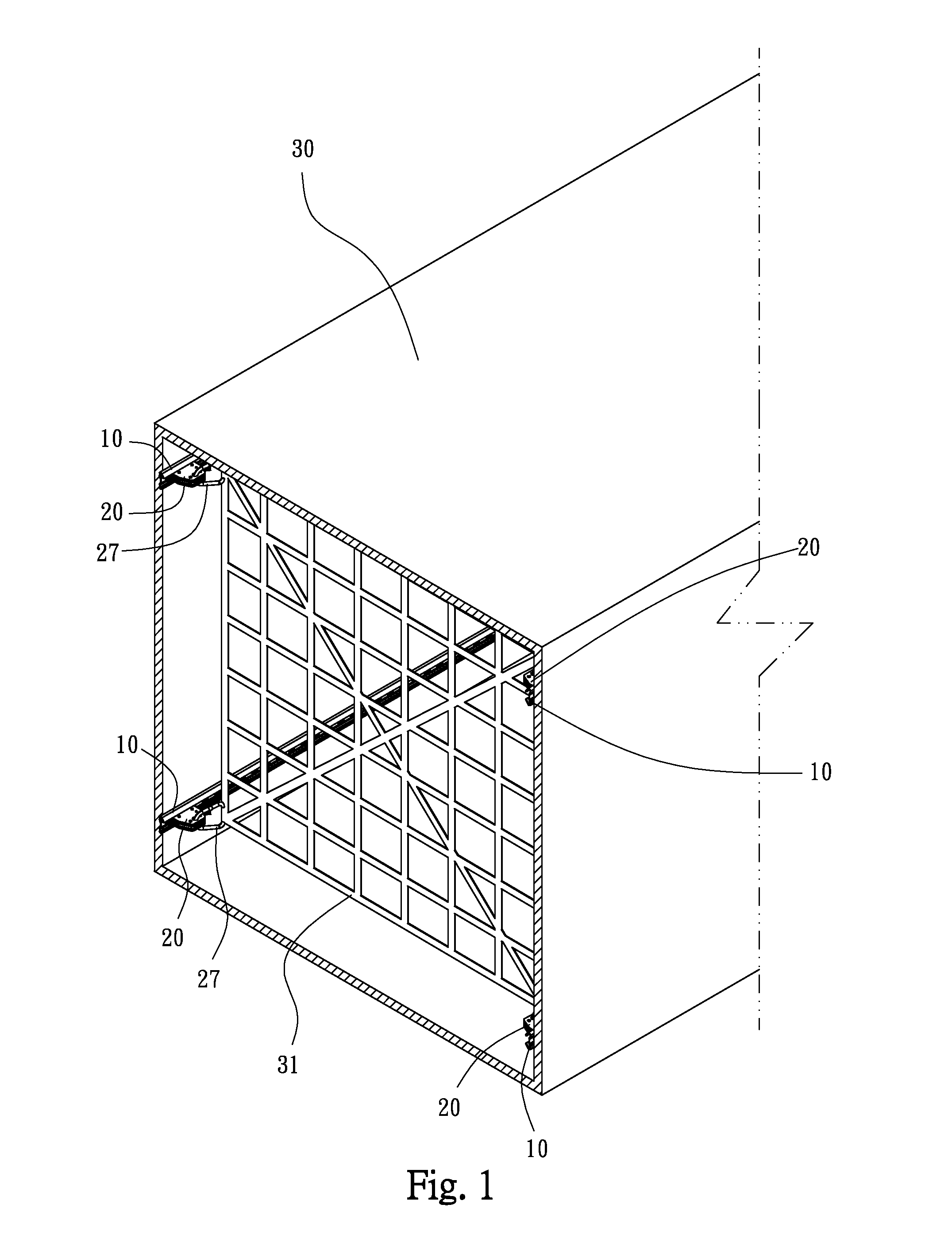
[0016]Please refer to FIGS. 1-8. The cargo restraint apparatus of the invention includes a track 10 and a fastener 20.

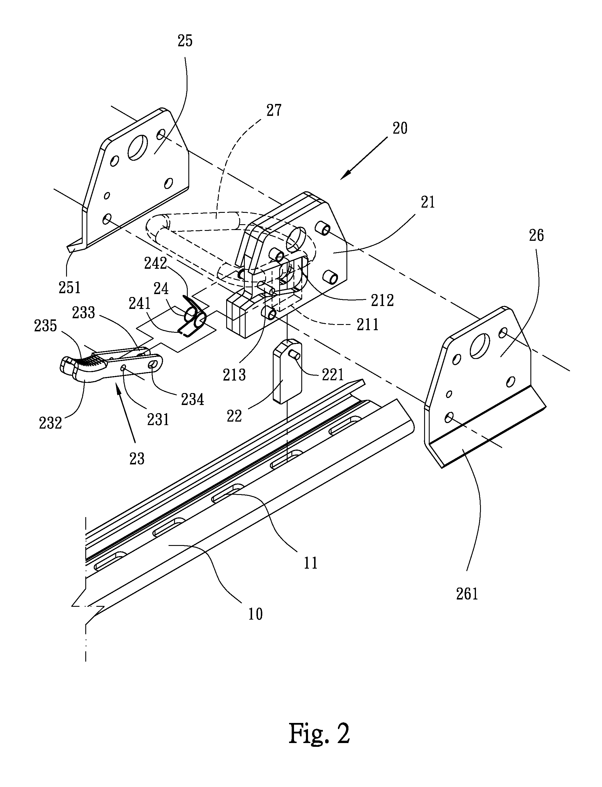
[0017]The track 10 has a plurality of engagement holes 11 at intervals and two inclined guide troughs 12, 13. The fastener 20 includes a seat 21, two guide plates 25, 26, an insert 22, a lever 23 and a torsion spring 24.

[0018]The seat 21 is provided with a sliding trough 211 perpendicular to the track 10 and a passage 212 connected to an end of the sliding trough 211. The two guide plates 25, 26 are outward inclined and separately fixed on two sides of the seat 21. Each of the guide plates 25, 26 has an inclined guide tongue 251, 261 toward the track 10. The two guide tongues 251, 261 are separately slidably received in the guide troughs 12, 13 for securing the fastener 20 on the track 10.

[0019]The insert 22 is received in the sliding trough 211. A shaft 221 is formed on the insert 22 and located in the passage 212. The lever 23 is pivoted on the seat 21. In detail, ...


PUM


Abstract

A cargo restraint apparatus for a cargo receptacle of truck is disclosed. The apparatus is composed of a track with engagement holes and a fastener. The fastener includes a seat with a sliding trough and a passage. Two guide plates are fixed on two sides of the seat. Each guide plate has an inclined guide tongue slidably received in the track. An insert is received in the sliding trough. A lever has a pivot hole at a center thereof for connecting to a pivot of the seat and a handle end and an action end are defined on two opposite sides of the lever. The action end is pivoted to the shaft. A torsion spring is disposed on the pivot and bears against the seat and the lever. The insert is normally engaged in one of the engagement holes.

Description

BACKGROUND OF THE INVENTION[0001]1. Technical Field[0002]The invention relates to cargo restraint apparatuses used in cargo receptacles of trucks, particularly to tracked cargo restraint apparatuses.[0003]2. Related Art[0004]A typical cargo restraint apparatus includes a track fixed on a wall of a cargo receptacle and a fastener slidably mounted on the track. The fastener is provided with first and second spring-loaded trigger members. Only one of the two trigger members can be released from the track in a direction, and the other one of the two trigger members can be released from the track in another direction.[0005]However, manufacturing costs of such a trigger member are expensive. Furthermore, a restraint apparatus requires two trigger members. This increases volume of the apparatus. When releasing the engagement holes, two trigger members need to be pressed and moved. Thus it is so difficult to operate the apparatus.SUMMARY OF THE INVENTION[0006]An object of the invention is t...

Claims


Application Information

Patent Timeline
IPC IPC(8): B60P7/08
CPCB60P7/08B60P7/0876B60P7/0815B60P7/14
Inventor CHOU, YEH-CHIEN
Owner STRONG YUN IND
Why Eureka
Eureka Blog
Learn More